Installing iLand
3-11
3
iControl DC
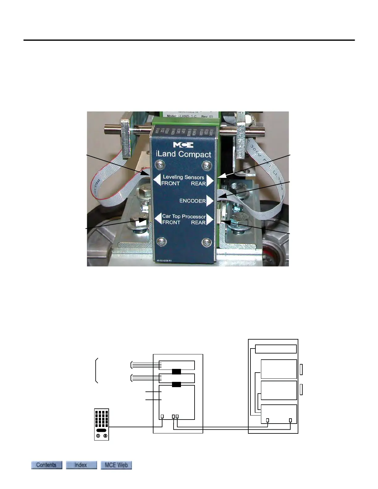
Cabling Connections
The Position Encoder and Leveling Sensors connect to the iLand Signal board (LS-IPH)
through short, factory-assembled cables with an RJ45 connector at each end. These cables
should already be in place and connected. If they have been removed, they need to be recon-
nected. Refer to Figure 7 for guidance.
Figure 7. iLand Cable Connections
The cables from the iLand Landing System (LS-IPH board) to the iLink Cartop Processor (ICE-
CTP board) are supplied (C-ETHERENET-BGE-XX). They should be routed through flexible
conduit from the iLand connectors shown in Figure 7 to the iLand Front Door and, if applicable,
iLand Rear Door connectors on the ICE-CTP board in the iLink Cartop Box as shown in Figure
8 (see also “iLink Wiring” on page 3-15).
Figure 8. Cartop Interconnection
Position Encoder
Rear Door
Leveling Sensor
(optional)
Front Door
Leveling Sensor
iLand to
iLink Cartop
Processor
Front Door
iLand to
iLink Cartop Pro-
cessor Rear Door
(optional)
Inputs
Outputs Field Outputs
Field Inputs
Discrete Car Calls
(if not Serial Car Call)
Cartop Board
(ICE-CTP)
iLINK CARTOP BOX
iLAND LANDING SYSTEM
Serial Car Call
Sensor Board
Sensor Board
Signal Board
(LS-IPH)
Front
Rear (option)
Position Encoder
Serial Link
Serial links to iControl
Load Weigher
Landing Zone
magnet
Landing Zone
magnet