iView - Controller View
9-102 Manual # 42-02-7223
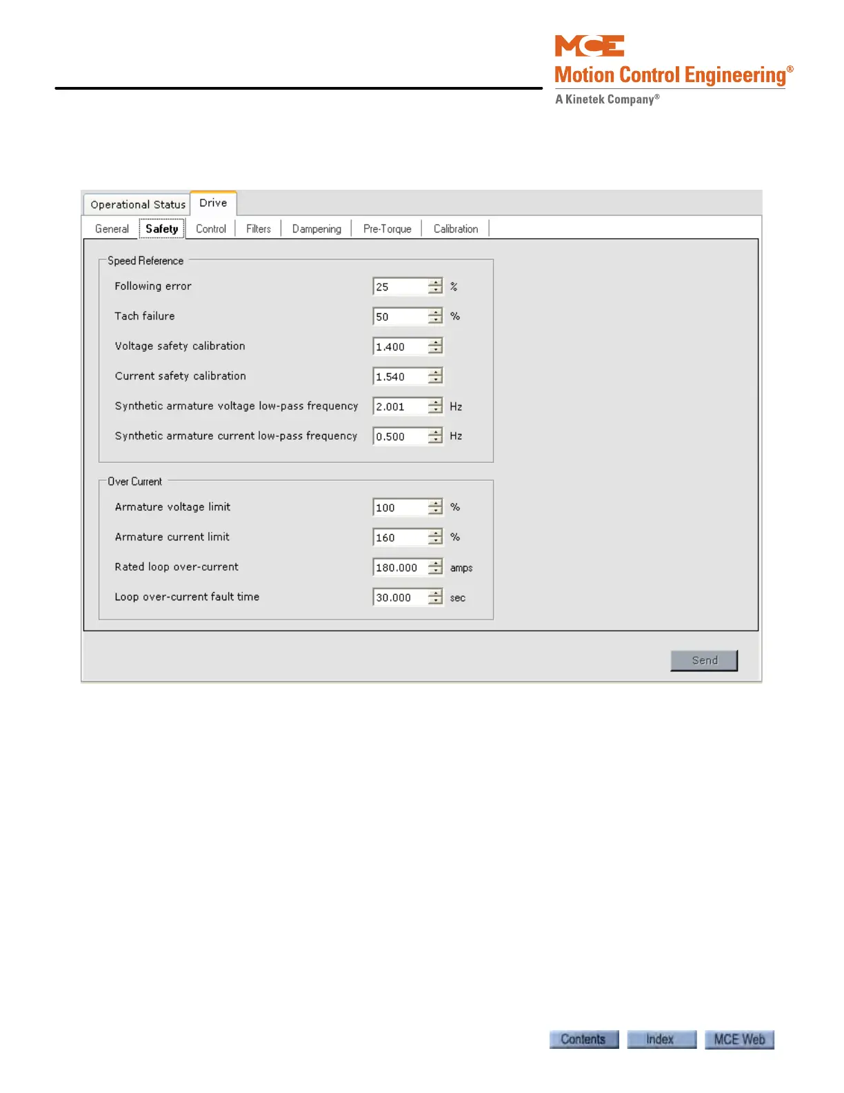
Drive - Safety Tab
Note: Depending on the Drive type selected on the Drive > General tab, some drive parameters
will be grayed out (not available for adjustment).
Speed Reference
• Following error: Adjusts amount of error permitted between voltage from Tach/Encoder
and pattern voltage. When set to 75%, a 7.5VDC error is allowed between the Tach/
Encoder and pattern voltages (100% = 10VDC). If excessive error is detected, a Tach Error
Fault will be displayed. Please refer to “Following Error Margin” on page 2-83.
• Tach failure: Percentage of error at which the system will assume a tach failure. Please
refer to “Tach Failure Calibration (System 12 SCR Drive)” on page 2-69.
• Voltage safety calibration: In conjunction with Current Safety Calibration, creates a car
speed signal independent of Tach, which is compared with the feedback speed to identify a
Tach failure. Increase to provide more armature voltage to the synthetic speed signal.
Please refer to “Tach Failure Calibration (System 12 SCR Drive)” on page 2-69.
• Current safety calibration: Compensates for loop circuit loss in creating the internal speed
signal from the armature current. Increase to increase DC loop current to the synthetic
speed signal. Please refer to “Tach Failure Calibration (System 12 SCR Drive)” on page 2-
69.