Construction Mode
2-10 Manual # 42-02-7223
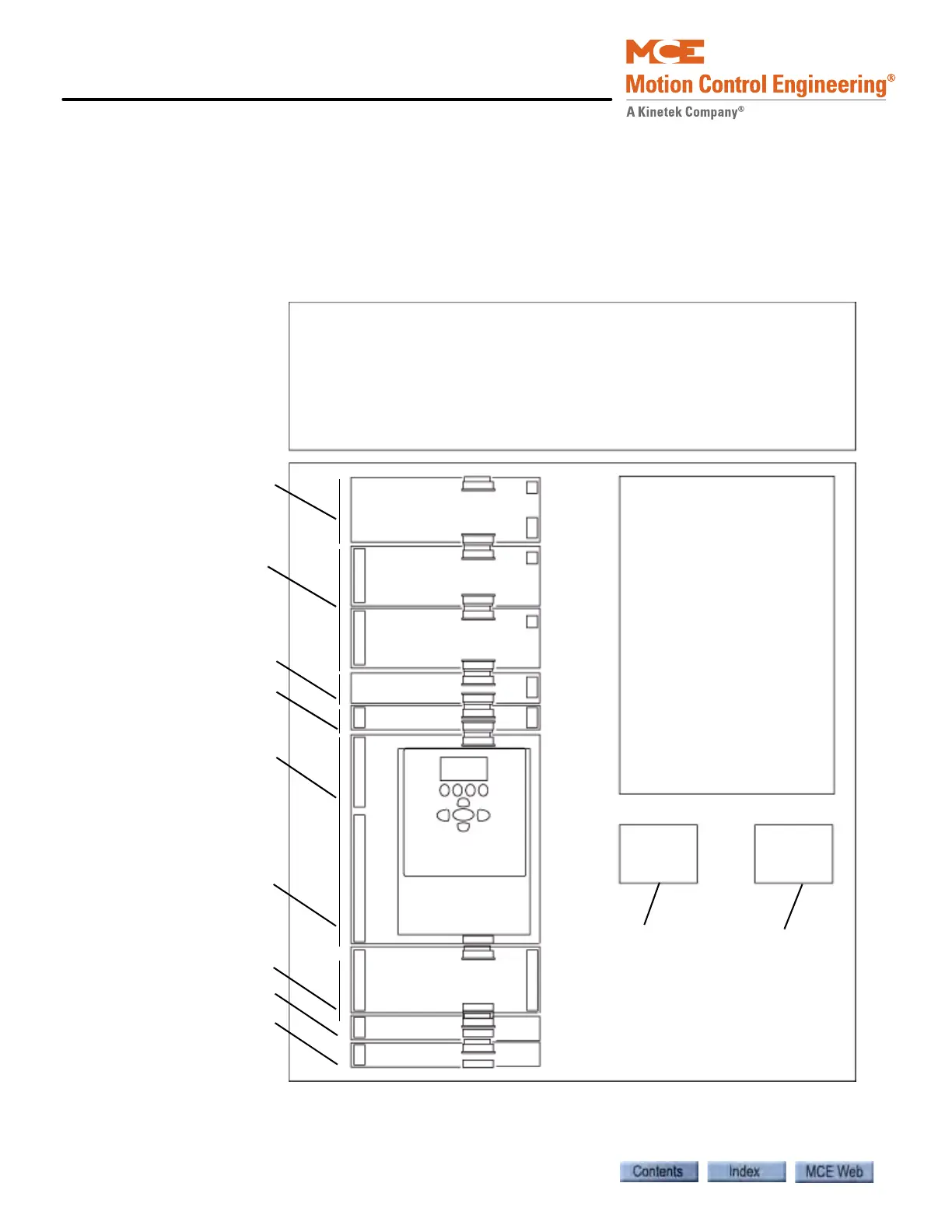
Overview of Typical Connection Locations
The following diagram provides a general overview of component and connection locations
inside iControl. Because circuit boards in iControl are connected along a common bus, they may
be arranged differently or different boards may be used in different installations. This is only a
general overview. Use it in conjunction with the job prints when making electrical connections.
Please refer to “iBox Field Connections” on page 11-7 for a list of specific inputs and outputs.
System 12 SCR Drive
(Note: Quattro DC
Drive is supplied in
a separate cabinet,
see next page)
iBox Panel
ICE-MOR: Outputs
ICE-MIAC: Inputs
ICE-SF: Srl. Fixtures
ICE-EQ: Earthquake
ICE-SAF: Safety Processor
ICE-IMP: Main
Processor
Contactor
Resistor Cabinet
Field wiring for hoistway,
car, landing and load
weighing systems, and dis-
crete hall calls are on the
left edge of the controller.
High voltage connections
are primarily on the right
side of the cabinet under
the DC drive (and in a
separate cabinet for the
Quattro drive).
Outputs used to drive
customer peripherals.
Signal/Pin assignments
made in iView screens.
Serial fixture interface.
Floor indicators, etc.
Earthquake sensor I/O.
Tachometer, position
encoder, velocity encoder,
and serial link from cartop
processor.
Discrete car connections,
limit switches, hoistway,
and door system connec-
tions.
Safety I/O.
Spare I/O. Common,
120VAC, and 110VDC
buses.
Motor contactor
wiring.
AC connections.
ICE-IRB:
ICE-MIAC: Inputs
Customer peripheral
inputs (card read-
ers,etc.) Signal/Pin
assignments made in
iView screens.
Emergency Brake
connection
Rear door processing
ICE-RG Rope Gripper
ICE-IRD Rear Door