iControl Circuit Board Quick References
6-115
6
iControl DC
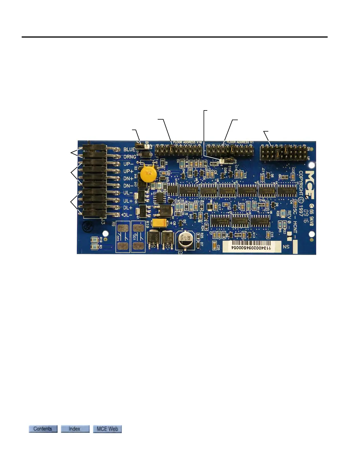
SC-HCNT Serial Hall Call Node Board
In a typical installation, an SC-HCNT Serial Hall Call Node board is mounted in each hall call
fixture enclosure. Please refer to “Hall Call Installation” on page 5-32. The board provides two
outputs to power the hall call lamps or LEDs, two inputs for the hall call buttons, and jumpers
to set the floor ID and hall call “type”.
Figure 6.18 SC-HCNT Serial Hall Call Node Board
For more information on setting the node board addresses, See “Setting Node Board Addresses”
on page 33..
JP1 Call Type
JP2 Floor Address X1
JP3 Floor Address X10
JP4 unused
Hall Call Bus
Power / signal
Up / Down
buttons
Up / Down
indicators
JP5 Future use