Drive Startup (Quattro DC Drive)
2-81
2
iControl DC
Running on Machine Room Inspection
Once you are satisfied that the brake is picking properly, verify proper car movement and motor
current. Troubleshoot movement if needed. Calibrate speed using a handheld tachometer.
Verifying Motor Rotation and Control (Quattro DC Drive)
1. On the Pattern > Common tab, set Pattern scaling = 100%.
2. Set the iBox Inspection switch to INSP and run the car using the Enable and Up (or
Down) switches.
3. Move the elevator on Inspection and verify that the motor is under control and rotating
in the proper direction.
4. If the motor is rotating under control in the proper direction, skip the remaining steps.
5. If the motor runs away in the proper direction, change C1-Encoder Connect direction.
6. If the motor runs away in the opposite direction, change C1-Motor Rotation direction.
7. If the motor runs under control in the opposite direction, change C1-Encoder Connect
direction and C1-Motor Rotation direction.
Verifying Pattern Command and Speed Feedback
1. Verify/set the following iView Drive parameters (View > Configuration > Drive > Gen-
eral tab > Speed Reference section):
• Reference type = Tachometer
• Scaling = 1.000
2. If you change any values, send them to the controller.
3. While running on Inspection, verify that D1-Speed Command is within about 1 fpm of
the requested inspection speed on Configuration > Pattern > Modes. Adjust A1 Spd
Command Mult if the speed is not correct (higher for increased speed).
4. Display the Virtual Oscilloscope (View > Diagnostics > Virtual Oscilloscope).
5. Set Test point 1 = Pattern (Command) and Test point 2 = Speed Feedback.
6. Run the car on Inspection and verify the polarity (Test point 1 and 2 traces are both
moving in the same direction). If they not, change the Speed Reference, Rotational
direction parameter (Forward / Reverse) on the Configuration > Drive > General tab.
7. Run the car and verify that the Pattern (Command) and
Speed Feedback (Test point 1 and 2 traces) are the same
amplitude. On the iView virtual oscilloscope (or a DVM
connected between STP1 and STP2), compare the Pattern
Command and Speed Feedback readouts. They must match
within 0.050 VDC while the car is running at steady state
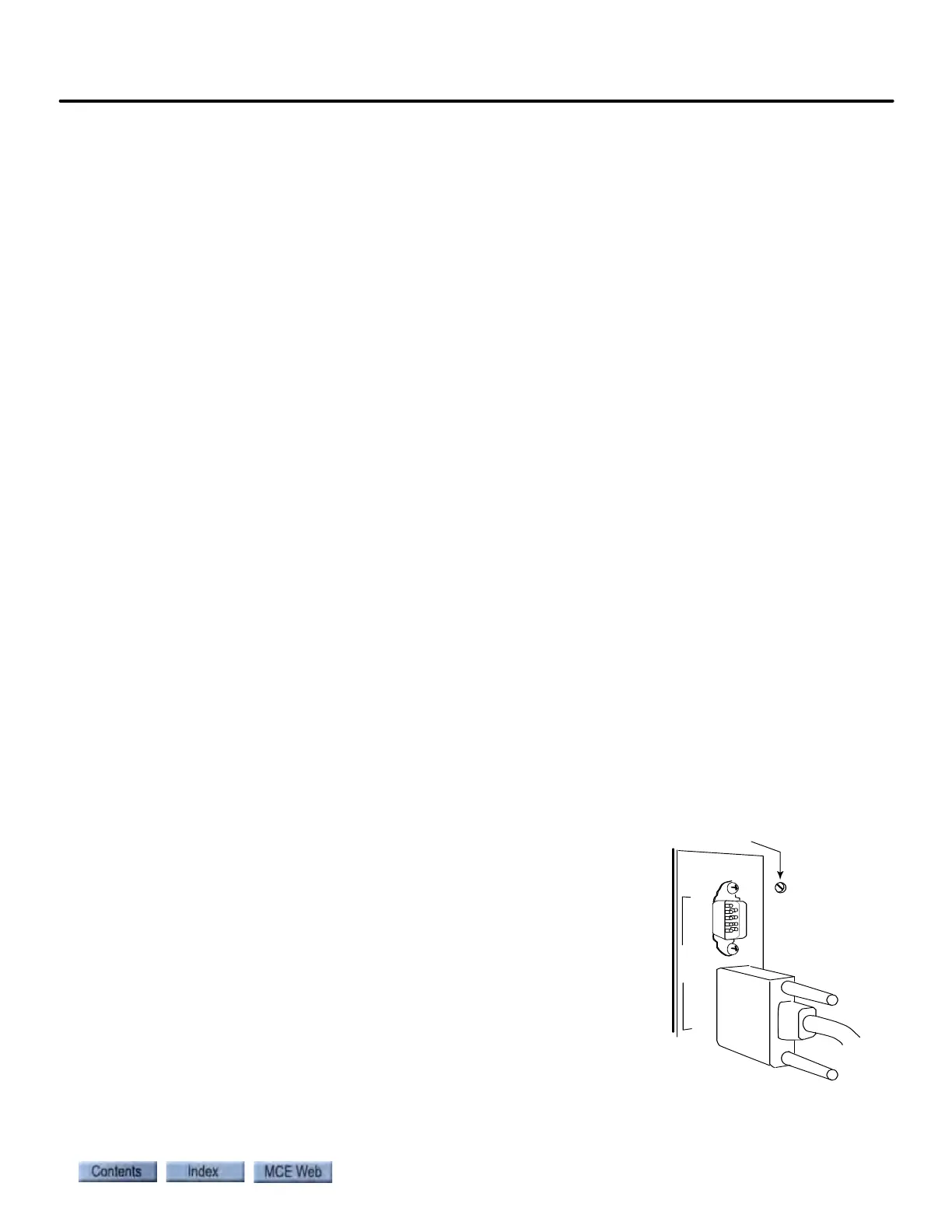
speed. If not, adjust the TACH ADJ trimpot (upper right
corner of iBox). The iPower Box door can be opened slightly
to improve access to the TACH ADJ trimpot. Turn the pot
slowly. This is a 15 turn trimpot, but the adjustment from
maximum to minimum on the virtual oscilloscope is less
than 1/2 turn.
If the trimpot adjustment is insufficient, adjust Scaling parameter up or
down in o.1 increments (Configuration > Drive > General tab > Speed
Reference section). Remember to Send the value to the controller, and then re-adjust the trimpot.