Synthetic Speed Calibration (System 12 SCR Drive)
4-15
4
iControl DC
Synthetic Speed Calibration (System 12 SCR Drive)
Calibration determines the value for the Voltage safety calibration and Current safety calibra-
tion parameters (Configuration > Drive > Safety tab). These in turn determine synthetic speed.
Calibration requires the elevator to move in both directions and to reach at least 50% of con-
tract speed in each. Actually reaching contract speed yields the best results. Additionally, move-
ment to both terminal landings will yield the best results.
Results can be verified using the Virtual Oscilloscope by observing the synthetic speed signal
(Synthetic Signal) on one test point in comparison to the speed feedback signal (Speed Feed-
back) on the other test point. When calibrated, shape and amplitude of the signals should be
similar.
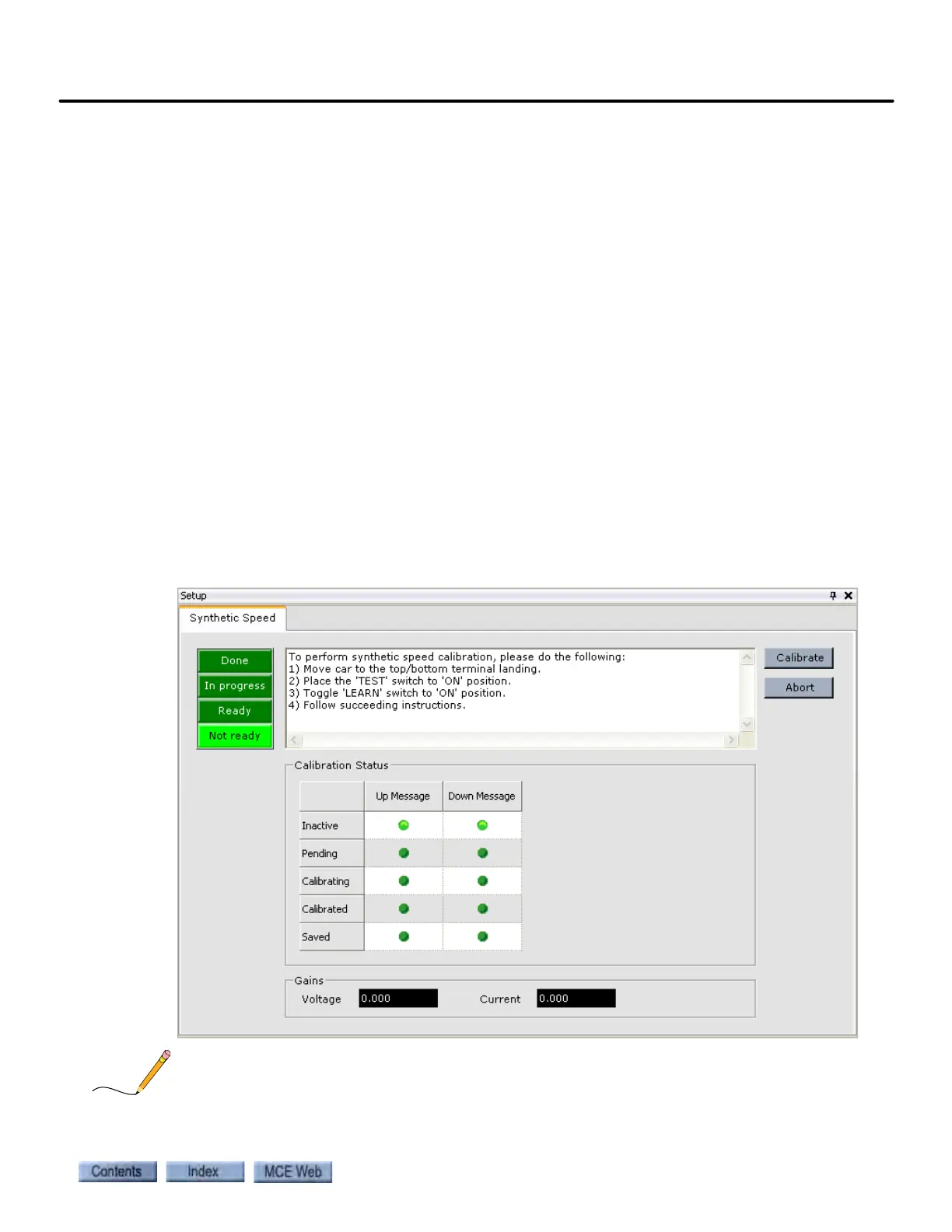
The Setup > Synthetic Speed tab displays the outputs that represent calibration results (Gains -
Voltage and Current). If these parameters were saved, Voltage safety calibration and Current
safety calibration parameters (Configuration > Drive > Safety tab) should be equal to these out-
put values.
1. Move the car to the top or bottom terminal landing.
2. Place the iBox TEST and LEARN switches in the ON position.
3. In iView, display the Setup > Synthetic Speed tab (View > Setup > Synthetic Speed).
4. Follow the instructions in the message window on the Setup - Synthetic Speed tab.
A manual version of this calibration process is described in Section 2. Please refer to “Tach Fail-
ure Calibration (System 12 SCR Drive)” on page 2-69.