iView - Controller View
9-28 Manual # 42-02-7223
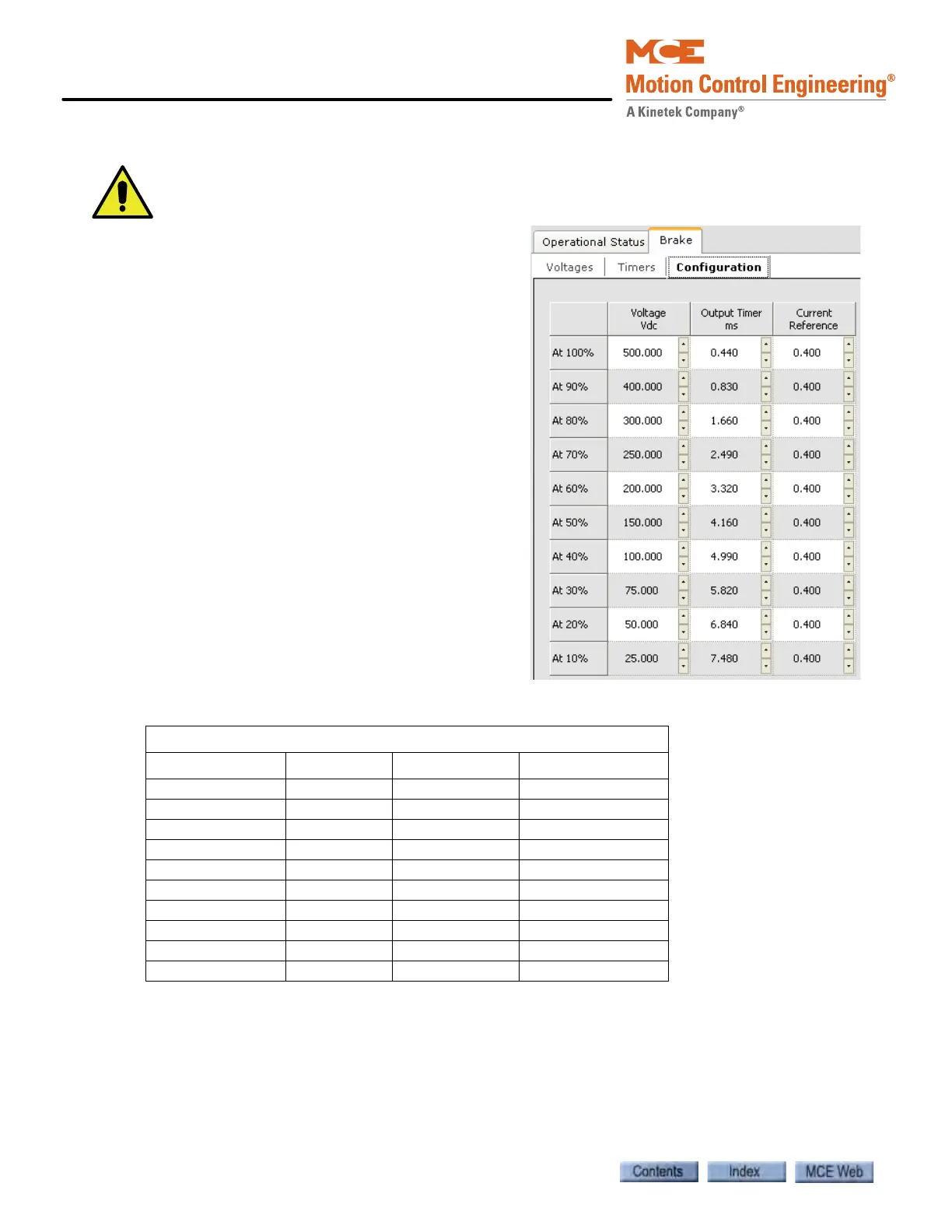
Brake - Configuration Tab
The parameters on this tab are set automatically
during brake calibration. Do not modify these
parameters unless advised to do so by an MCE
representative.
• Voltage: The voltage output to the brake coil
at various percentages of maximum voltage,
measured during calibration (see Caution
above).
• Output Timer: The amount of OFF time
during each cycle (delay before turning on
the brake output) required to output the
appropriate voltage to the brake coil at vari-
ous percentages of maximum voltage (see
Caution above).
• Current Reference: The voltage feedback
that represents the brake current at various
percentages of maximum voltage, measured
during calibration (see Caution above).
Table 9.3 Typical Configuration Values for 300V AC Brake Supply
Typical Values for a 300VAC Brake Supply
Percent of V max Voltage VDC Output Timer Current Reference
At 100% 249.639V 0.100ms 0.243V
At 90% 225.484V 2.084ms 0.214V
At 80% 200.253V 2.852ms 0.194V
At 70% 174.083V 3.492ms 0.171V
At 60% 149.155V 4.608ms 0.149V
At 50% 125.508V 4.580ms 0.128V
At 40% 99.164V 5.156ms 0.105V
At 30% 73.632V 5.735ms 0.082V
At 20% 49.092V 6.308ms 0.069V
At 10% 25.041V 7.012ms 0.040V