Construction Mode
2-22 Manual # 42-02-7223
Verifying Brake Current Resistance
High current brake systems use a brake (iField) module.
1. With brake leads disconnected from the controller, measure resistance through the
brake coil.
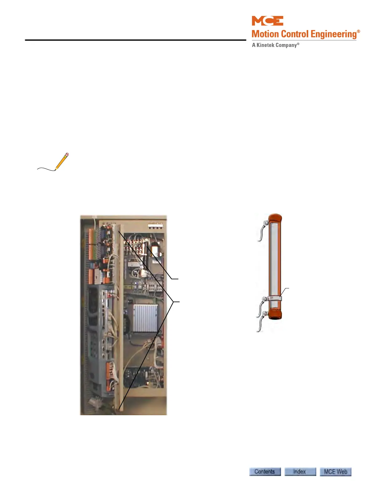
2. Inside the controller cabinet, locate the screws, one at the top and one at the bottom
right corner of the iPower box (the enclosure the iBox is mounted to). Turn the screws
counter-clockwise to their stops and open the enclosure (it is hinged on the left).
3. Refer to job print drawing D2. Toward the right-top of the enclosure, locate the large
ceramic resistor labeled RB.
4. Check the resistance across RB. As an initial working value, RB resistance should be
about three times (3 X) the resistance measured across the brake coil.
During adjustment, the resistance across RB may be further adjusted to achieve smooth brake
setting. Refer to job prints for instructions.
5. If necessary, adjust RB resistance by loosening and sliding the center-tap up or down.
When the resistance is correct, retighten the center tap.
The controller i Power
box release screws
are in the top and
bottom right corners
of the enclosure. Door
must remain closed
during operation.
RB is a large,
ceramic resistor with
a center tap.
Loosen and slide
the center-tap
ring to change
resistance.
RB is in this area