Construction Mode
2-12 Manual # 42-02-7223
Peripheral Inputs and Outputs
In every installation, there are different requirements for accepting inputs from or providing
outputs to various kinds of peripheral equipment. iControl handles this generic need using ICE-
MIAC input boards, ICE-MOR output boards, and ICE-COP and SC-ION serial I/O boards.
Typically an installation will have at least one MIAC and one MOR board in the controller cabi-
net to handle requirements local to the machine room and at least one MIAC and one MOR
board in the cartop interconnect box (iLink) to handle requirements local to the elevator car.
Inputs Refer to your job prints (drawings -9 — nn or -CT) to see exactly how your periph-
eral inputs are configured. Typical usages include car call buttons, card reader inputs, fire
return switches, smoke sensors, etc. To complete an input, the installer wires a switch or con-
tact closure provided by the peripheral equipment between a power bus (120 VAC) and one of
the ICE-MIAC board input connections. Exact requirements are collected during the job survey
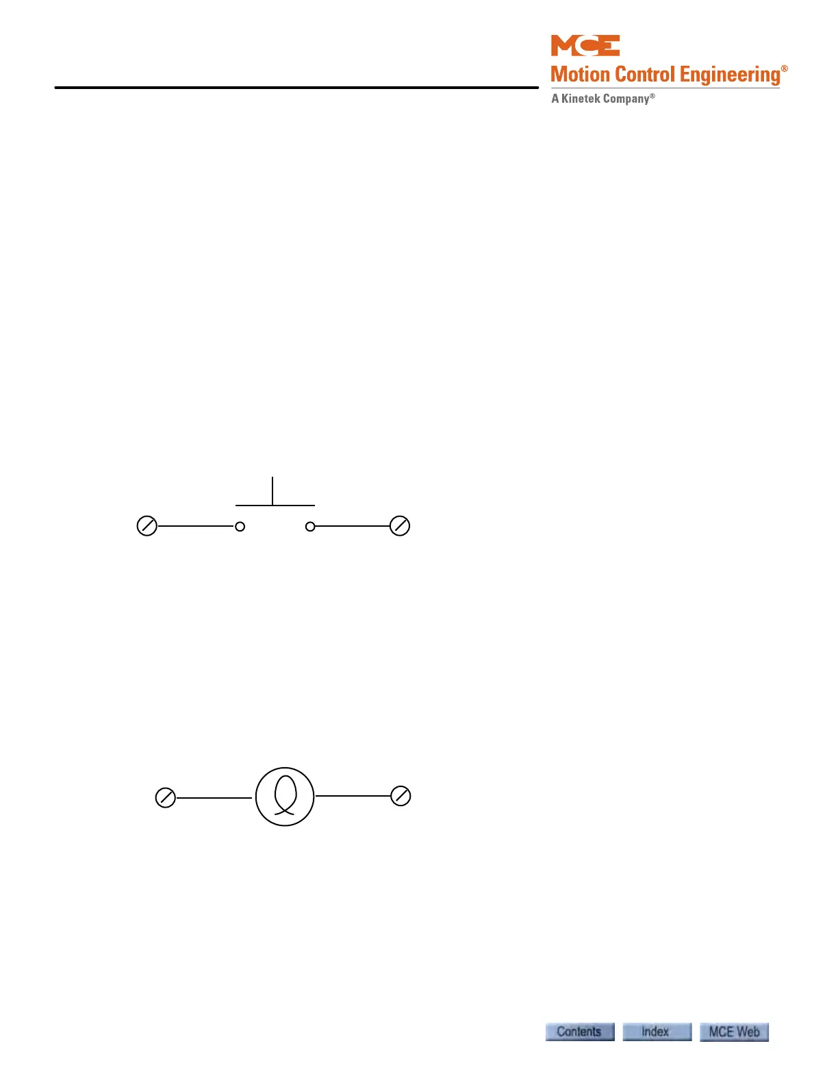
and documented in the job prints. The illustration below shows a typical switch wiring example.
Figure 2.2 Typical Peripheral Switch Connection to ICE-MIAC Board
Outputs Refer to your job prints (drawings -9 — nn or -CT) to see exactly how your out-
puts are configured. Typical usages include in-service lights, emergency power lights, nudging
buzzers, floor chimes, car-riding lanterns and chimes, and car call button indicators (lights). To
complete an output, the installer wires the lamp, buzzer, etc. between a power bus and one of
the ICE-MOR output connections. Exact requirements are collected during the job survey and
documented in the job prints. Different blocks of outputs may be connected to different buses.
The illustration below shows a typical (lamp driving) output wiring example.
Figure 2.3 Typical Peripheral Lamp Connection to ICE-MOR Board
Power Bus
Input
Peripheral or
COP switch