Construction Mode
2-26 Manual # 42-02-7223
Velocity Encoder Installation and Wiring
(If you are using a tachometer, please see the preceding topic.) The encoder must be mounted
and wired according to the drawings. When installed, the encoder must be electrically isolated
from the motor or any other ground. (Resistance between the encoder casing and the motor or
other ground should be “infinite.”)
Do not mount the encoder or its wiring close to a magnetic field (the motor or brake coils). Mag-
netic fields can induce AC into the encoder signal, producing erratic control at lower speeds.
Encoder wiring must use a separate, grounded conduit. Inside the controller cabinet, if control
wires must cross power wires, they must cross at right angles to reduce the possibility of inter-
ference.
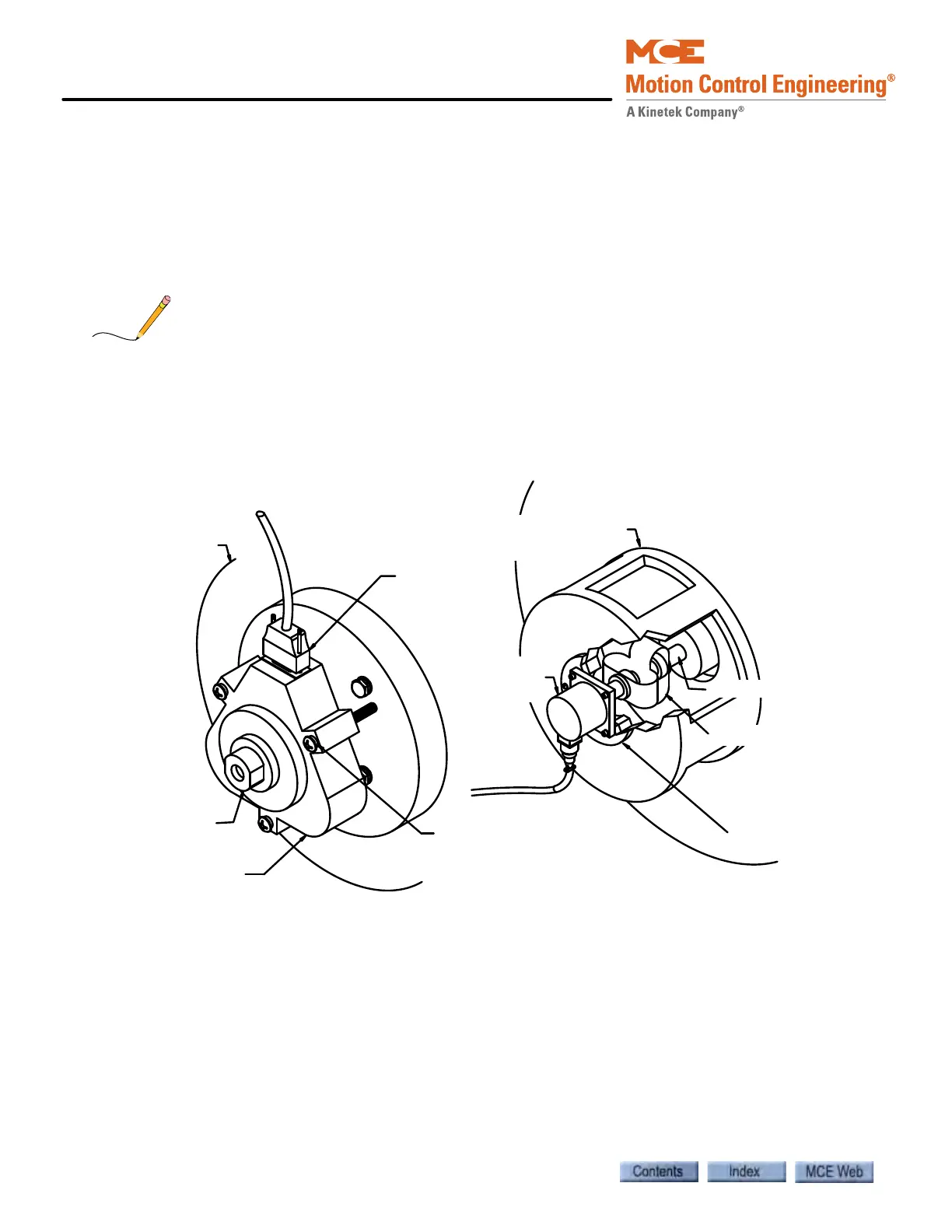
Encoder Mounting The following illustration shows two typical encoder installations.
Figure 2.9 Typical Encoder Installations
It is very important that the encoder does not slip, wobble, bounce, or vibrate due to poor instal-
lation of the shaft extension, coupling, or encoder mounting. It is also important that the
encoder housing be electrically insulated from the motor, machine, or other ground if the
encoder is manufactured by BEI. An insulated encoder mount has been furnished with the BEI
encoder. However, this type of mounting may not be practical for all applications, therefore, the
best method for mounting the encoder and coupling it to the motor must be determined at the
job site.
Hoist motor
9-pin D
Connector
Isolator
bushing
Velocity Encoder
Hoist motor
shaft
Typical mounting
bracket
Velocity
Encoder
Phenolic
isolator
Flexible coupling
Hoist motor shaft