Drive Startup (System 12 SCR Drive)
2-63
2
iControl DC
Current Limit Adjustments (System 12 SCR Drive)
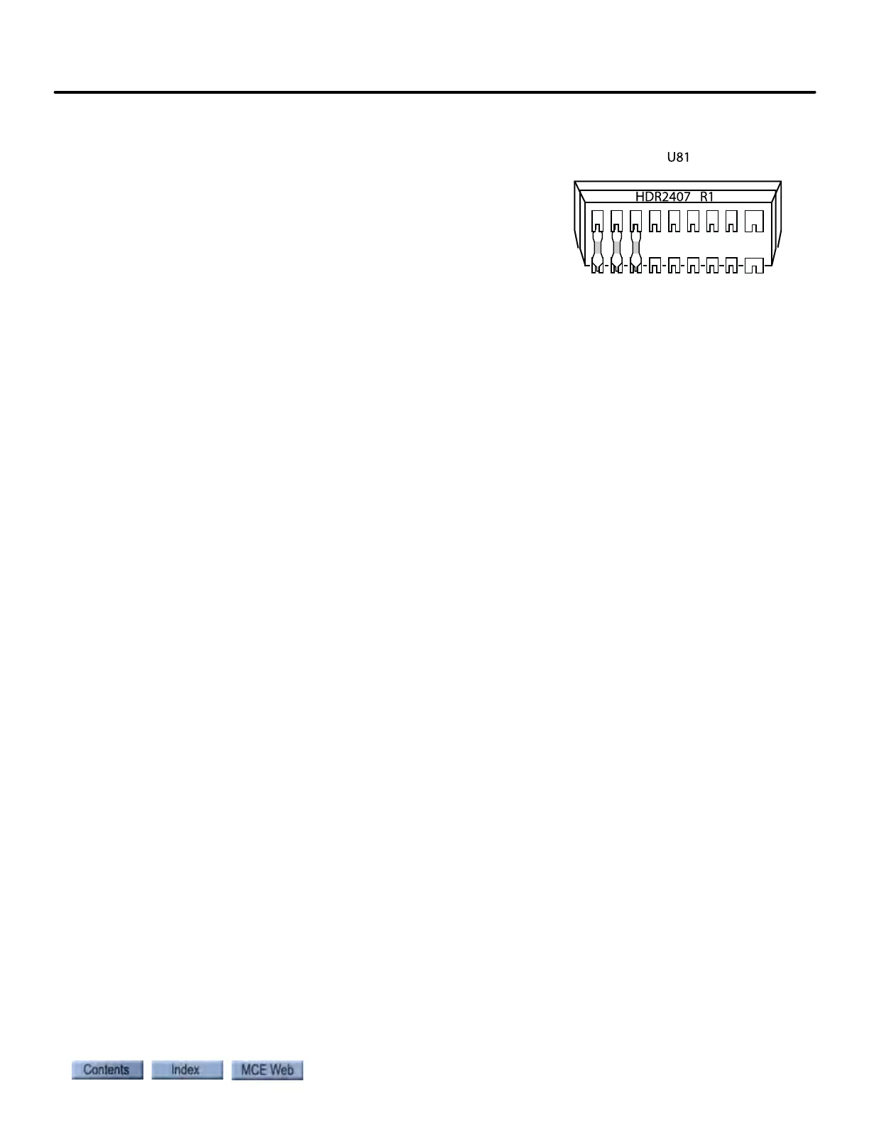
This section describes making current limit adjustments for the
System 12 drive. Drive voltage and current capabilities are tai-
lored to the needs of the job by placing a specific “header” in
socket U81 on the drive SCR-LGA board. The header is labeled.
For example, “HDR2407” in our example.
The first two numbers represent armature voltage; the last two
represent the armature current for which the drive is set. Only
the most significant two digits are used to represent values. For example, 24 and 07, indicate
240V and 75A respectively. Loosen the four captive screws holding the System 12 Drive cover in
place and remove the cover.
The large circuit board at the top of the drive is the SCR-LGA board. The header is approxi-
mately at the top, center of the board.
• Check the header label and verify that it looks correct for the hoist motor being used on
this job. (Motor plate armature voltage and armature current labels approximately
“match” the drive header label.)
The drive header label should also match the armature voltage and current specifications shown
in the prints for the job (see Output Ratings on page -D1).