Inspection Mode
3-18 Manual # 42-02-7223
iLink Power Connections
The iLink cartop interconnect box receives operating power from iControl through the travel-
ling cable. Typically, the power wires are connected to the terminal strip in the cartop box and
distributed from there to the circuit boards. Connections between the terminal strip and the
boards are made at MCE before shipment but must be verified during installation.
1. Refer to the initial pages of the -CT job print drawings.
2. Connect the power buses as shown, using the wire types specified. The power delivered
to the cartop box depends upon the needs of the installation. Refer to the -1 and -TW
drawings for details.
Car Operating Panel Connections
The Car Operating Panel control/power connections are made to the iLink cartop box.
1. Refer to the ICE-MIAC and ICE-MOR areas in the -CT drawings of the job prints.
2. Connect all inputs and outputs as shown.
3. If this installation is using Serial COP, see additional instructions. Please refer to
“Installing the Serial COP System” on page 3-22.
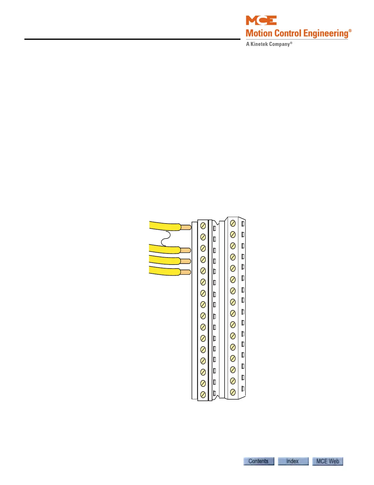
The drawing below shows terminal order used on both the ICE-MIAC and ICE-MOR boards.
Figure 3.2 ICE-MIAC and ICE-MOR Cartop Board Field Connections
#1
#16
#17
#32
Circuit Board
edge