System Options
5-12 Manual # 42-02-7223
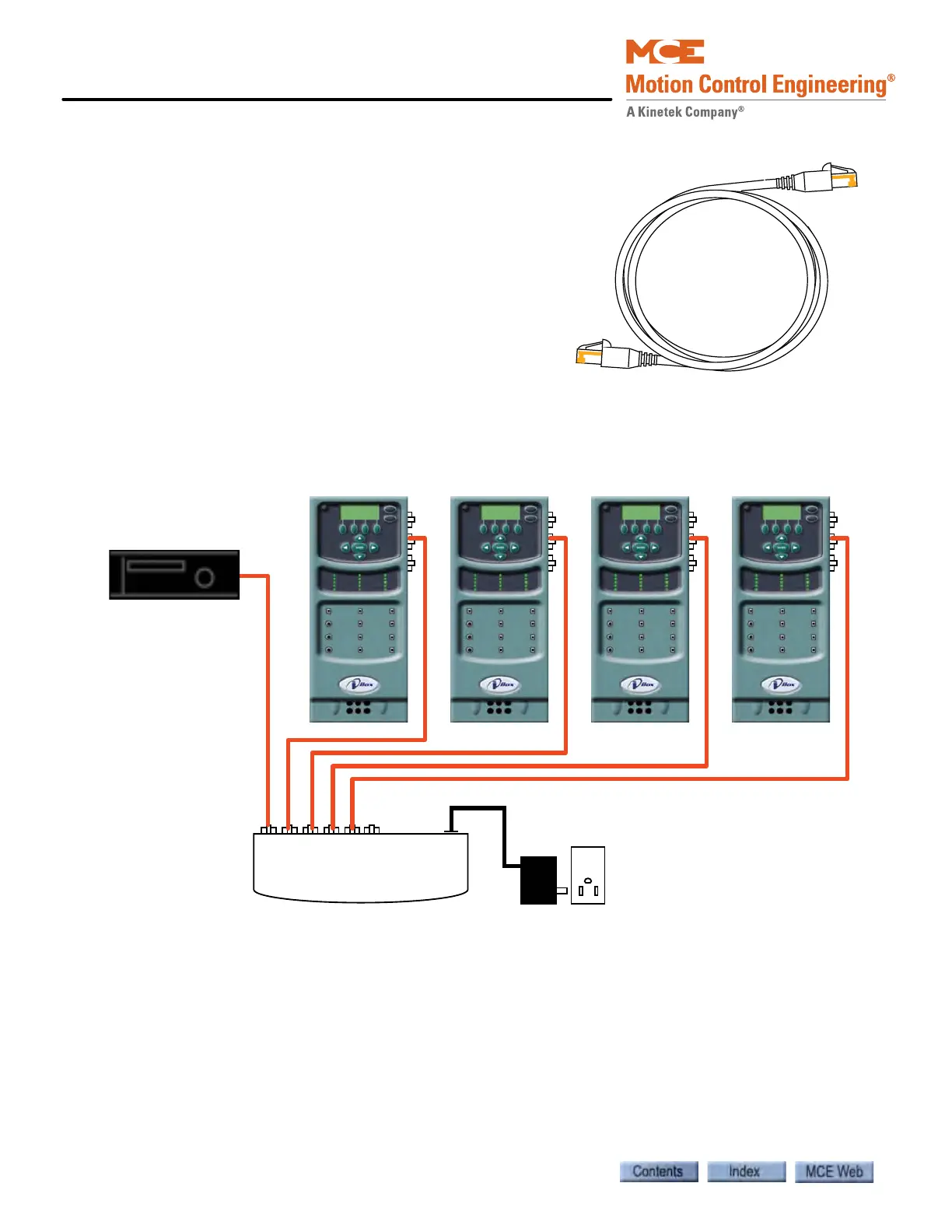
System Hub/Switch
The System hub/switch connects iCue to the iControls
in its group, to Serial Hall Call drivers through SC-HCE-
ME modules, and to SC-ION input/output expansion
boards. The Serial Hall Call and input/output expansion
board connections are completed at the factory before
the system is shipped and need only be checked to make
certain they are in place. Orange Ethernet cables are
used for connections to the System hub/switch. (The
LAN hub/switch cables are blue.) The cables have a
shielded RJ-45 connector at each end.
1. Connect the group and car controllers to the Sys-
tem hub/switch as shown in the illustration
below and in the MCE job prints. The job prints are the controlling document.
Figure 5.8 Typical System Ethernet Connections
2 2 2 2
iCue (typical*)
System Hub/Switch
System Hub
Power Plug
*The iCue computer in
your cabinet may be
different than the one
shown. The connection
for the System Hub/
Switch is labeled
SYSTEM.