Inspection Mode
3-16 Manual # 42-02-7223
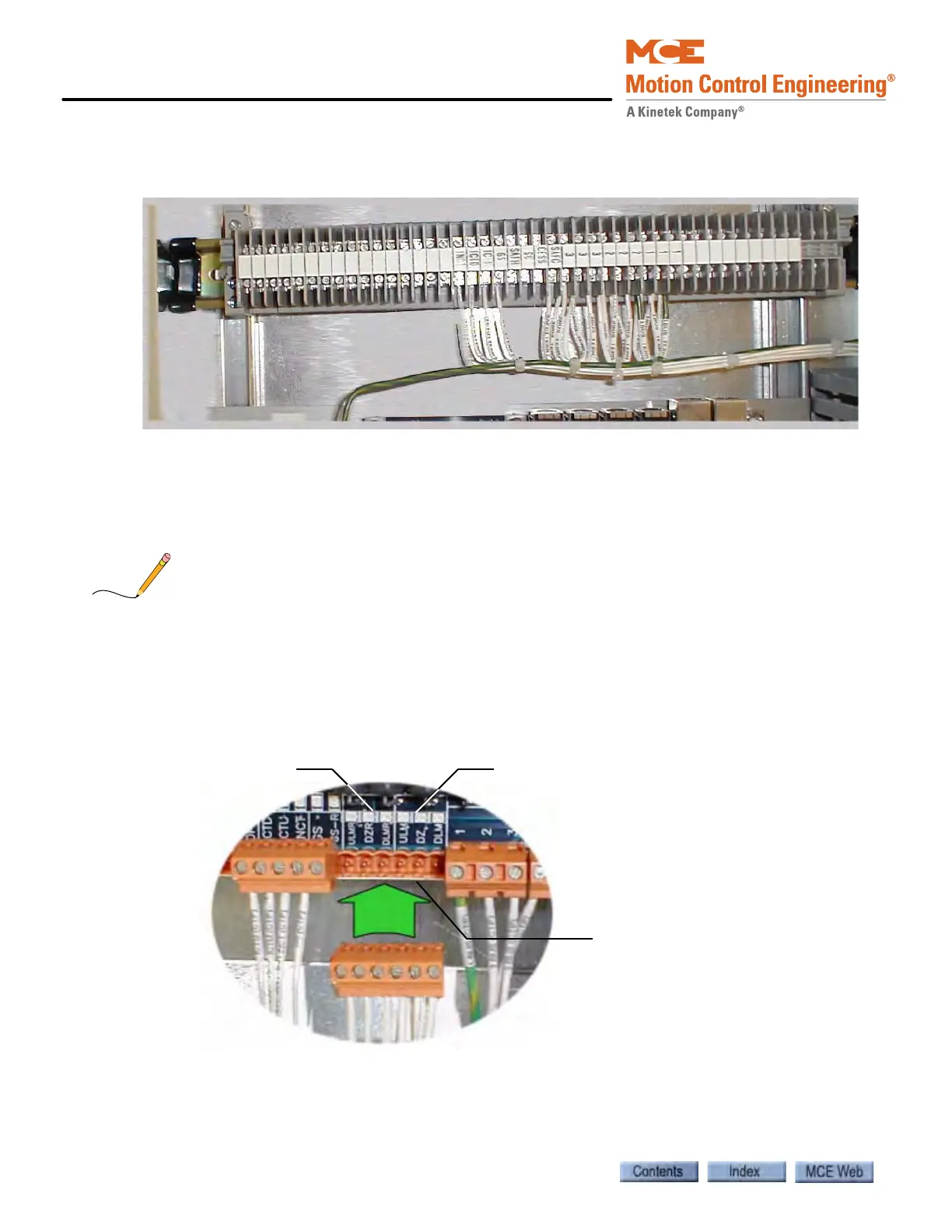
A “terminal strip” is mounted in the enclosure. The job prints provide details of terminal strip
wiring. A typical terminal strip is shown below.
Front and Rear Door and Leveling Signals
1. Refer to the -CT drawings in the job prints.
2. Connect front and rear door signals as shown.
These instructions assume that the door operator has been installed in accordance with the
manufacturer documentation.
Leveling Signals
1. Refer to the -CT job print drawings.
2. Connect the DZ, DLM, and ULM signals between the iLink CTP board and iControl/
iBox for front and rear (if present) doors as shown.
Level signals, Front
Level signals, Rear
iLink CTP edge connectors to
traveller