Software Testpoint Signals
11-3
11
iControl DC
Software Testpoint Signals
The iBox allows you to select any one of over fifty signals to display on-screen in iView or on the
iBox LCD display at each of two “software test points.” A signal selected on a software test point
(Test Point 1, Test Point 2) is also output on the corresponding iBox physical test point (STP 1,
STP 2). For example, if you selected Brake Voltage on software Test Point 1, the Brake Voltage
value would be displayed on screen and would also be output on iBox test point STP 1. Signals
you can choose from are listed in the following table.
Raw signals are unprocessed signals directly from a source. They are frequently too “spikey” to
use to read an average value but provide proof of activity and instantaneous reaction to chang-
ing conditions.
Filtered values represent the average, filtered value extrapolated from the raw signal to provide
a viewable, “smoothed,” signal.
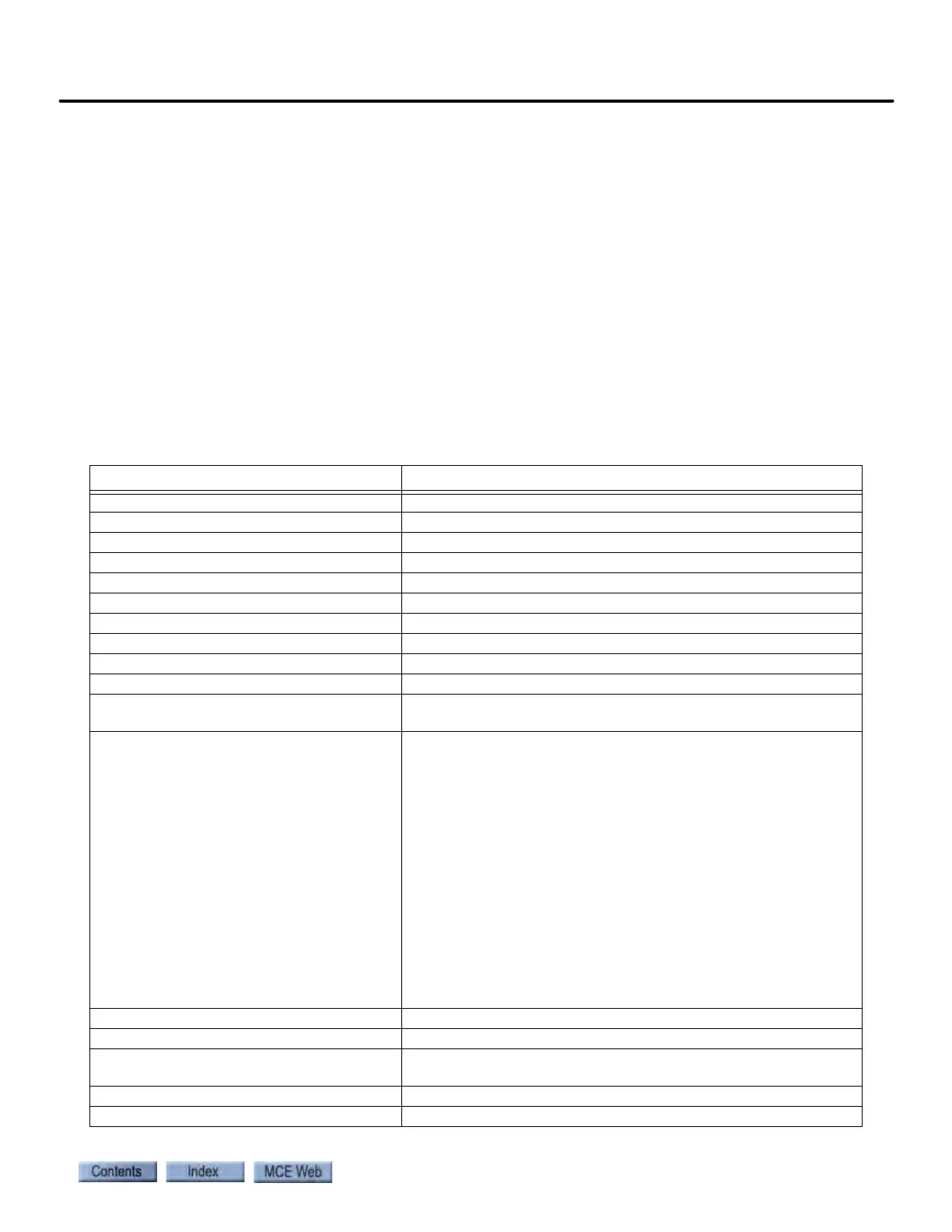
Table 11.2 Test Point Signals
Test Signal Description / Text References
Acceleration (Command) Post-filter, acceleration command signal.
Acceleration (Directional) Directional acceleration signal.
Acceleration (Filtered) Pre-filtered acceleration signal.
Acceleration (Interpolated) Interpolated (smoothed) acceleration signal.
Acceleration (Raw) Raw acceleration signal.
Acceleration (Slew) Slew rate limited acceleration signal.
Armature Active Status High = armature control enabled.
Armature Command Control Filtered armature composite command.
Armature Command (Damped) Damped armature composite command.
Armature Command (Raw) Raw armature composite command.
Armature Composite Control The summation of Armature Command Control and Armature
Feed forward Control.
Armature Control Set PID control sets that reflect standard, start (normal), stop (nor-
mal), steady-state (normal) and start (relevel) adjustment
parameters. Please refer to “Drive - Control Tab” on page 9-104.
Normal:
0 = Idle - before motor contactor picks [PID - Standard]
1 = Idle - after motor contactor picks [PID - Start (normal)]
2 = Acceleration [PID - Standard]
3 = Peak [PID - Steady-State (normal)]
4 = Deceleration [PID - Standard]
5 = Flare [PID - Stop (normal)]
6 = Leveling [PID - Standard]
7 = Idle - before motor contactor drops [PID - Standard]
Relevel:
8 = Idle - before motor contactor picks [PID - Standard]
9 = Idle - after motor contactor picks [PID - Start (relevel)]
10 = Acceleration - Leveling [PID - Standard]
Armature Current Dampen Feedback Armature current dampening signal.
Armature Current Signal Raw armature current feedback signal.
Armature Current Synthetic Feedback Armature current synthetic speed signal used for internal speed
reference and for current safety calibration.
Armature Differential Command Armature differential command.
Armature Differential Gain Armature differential gain.