System Options
5-62 Manual # 42-02-7223
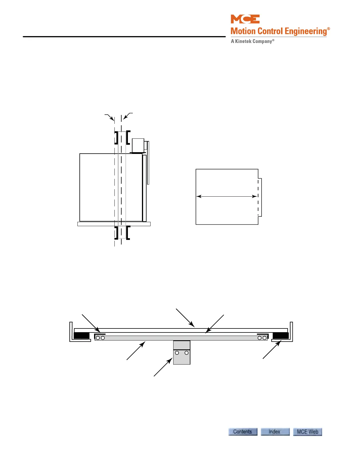
Installation Method #1 — Preferred
When installing, remember that the car is supported near the center of gravity. The center of
gravity may be offset towards the front of the car to compensate for door operator weight unless
the car has both front and rear doors. Install the target bracket as close to the center of the floor
as possible.
Figure 5.2 Center of Gravity vs. Center of Floor
To measure the compression of the rubber pads and not the sagging of the floor – attach a
structural piece such as a 1 ½” by 1 ½” angle to the outside edges of the floor.
Figure 5.3 Sensing the Edges of the Floor (compensation for floor sag)
Center of gravity, when empty
Center of the floor
Door operator
Front of
elevator
Floor Plan
(Top View)
Front of
elevator
Distance ‘A’
Support assembly attaches at
edge of floor to eliminate “sag
interference”
Isolated elevator
floor
3/8” air gap allows floor to sag
without affecting target bracket
Rubber pads support
isolated floor
Target bracket
Support Assembly
for target bracket