MCE Load Weigher
5-63
5
iControl DC
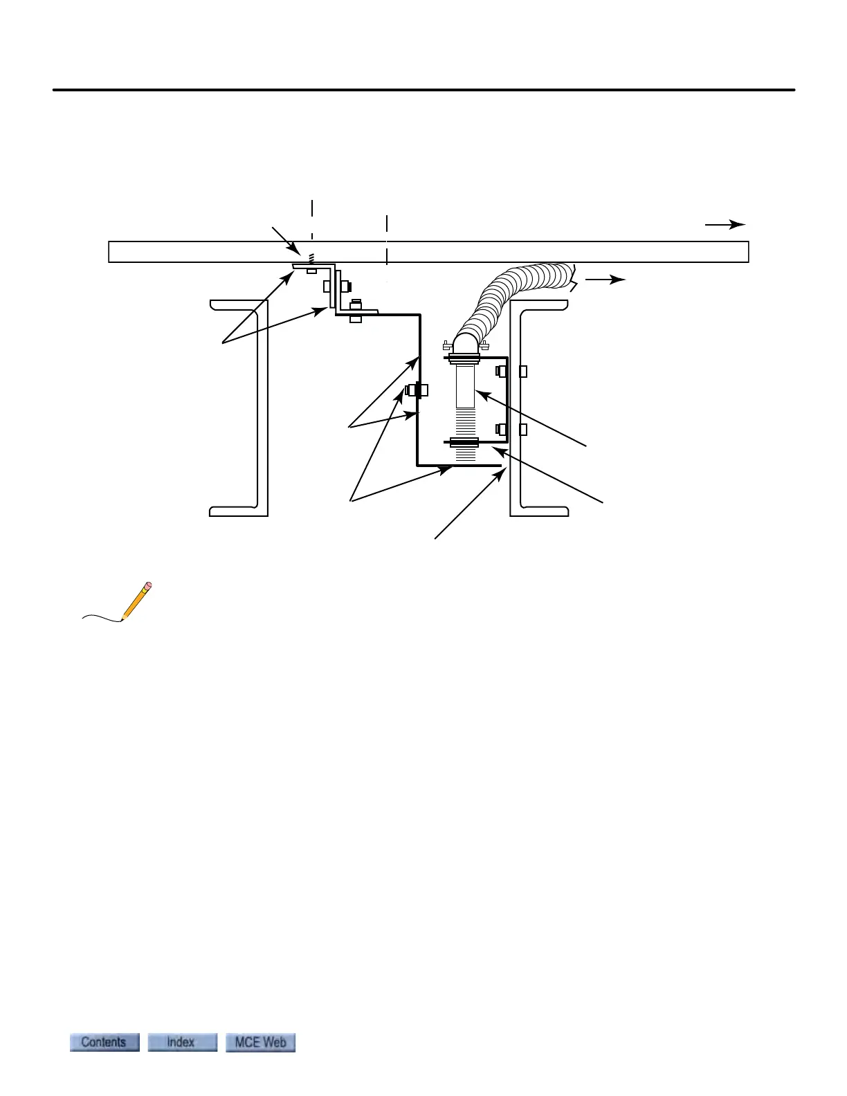
Figure 5.4 Target Bracket and Sensor mounted on Support Assembly and Car frame
The position sensed is where the support assembly for the target bracket is attached to the floor,
NOT where the sensor is located.
These screws hold the 2 small
angles to the bottom of the floor -
minimum 2 screws per angle.
Screws must be short enough to
avoid punching through the floor.
Center of Floor
Center of Gravity
Front of car
FLOOR
Support Assy
2 short pieces of
angle and 1 long
piece of angle
Target
Bracket
(2 pieces)
Adjustment bolts
for setting 1/16”
clearance between
sensor and target
bracket
Conduit to iLink
Proximity sensor
Sensor bracket
Maintain a 1/4” space between target
bracket and channels