Inspection Mode
3-12 Manual # 42-02-7223
iLand Status LEDs
The iLand signal board enclosure reveals status LED sets for the front and rear floor leveling
sensors and the position encoder sensor. Refer to the illustration below.
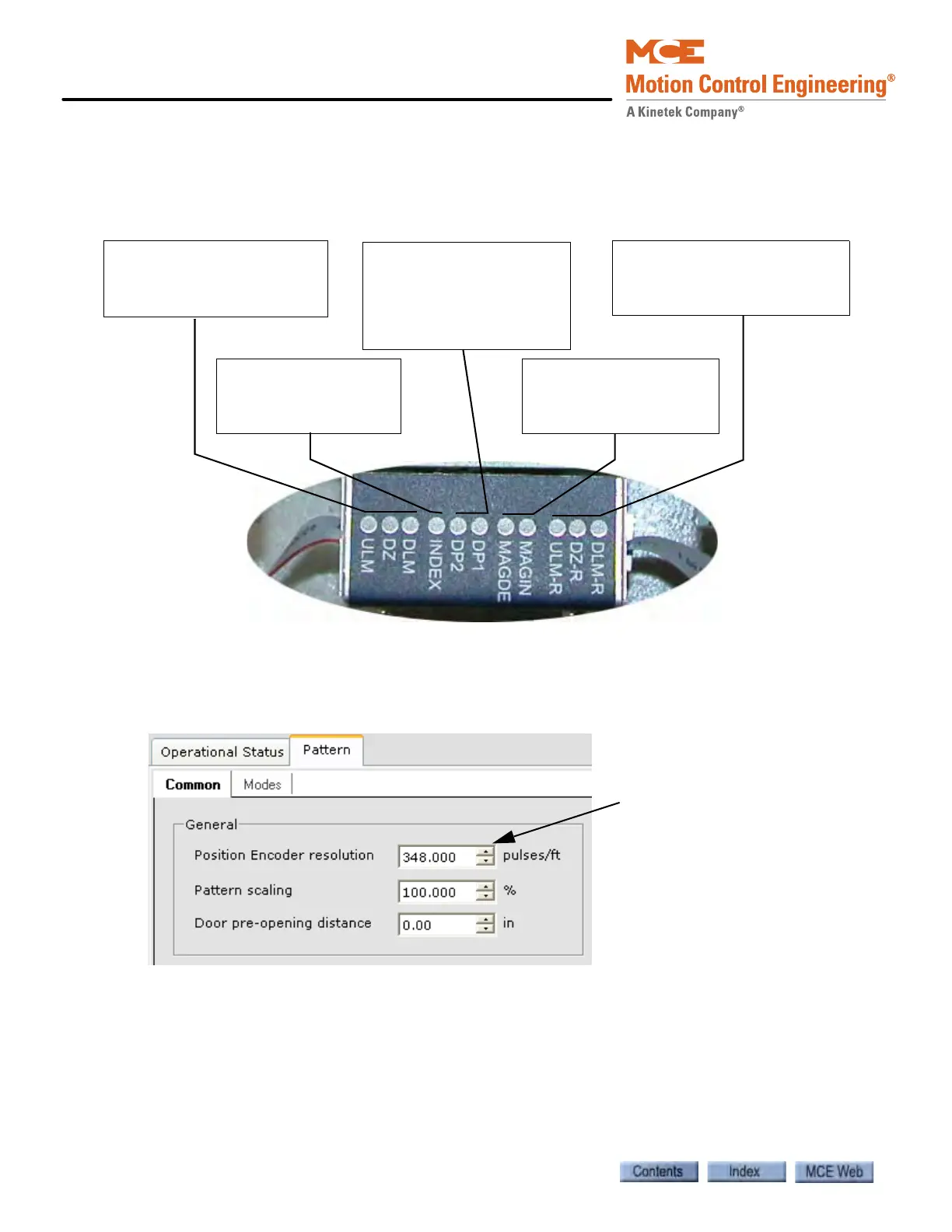
Figure 9. iLand Status LEDs
Setting the Position Encoder Resolution parameter
For the iLand Compact landing system, the Position Encoder resolution parameter must be set
to 348 pulses per foot (iView Controller > View > Configuration > Pattern > Common tab).
Calibrating the Floor Offsets
This is the final step to installing the iLand Compact Landing System (see “Calibrating the floor
offsets” in Section 4 of the User Guide). If this is a new installation, it is best to wait until the car
has been fully adjusted so that it stops consistently and accurately at the floors. When replacing
an iLand-H Landing System, the adapter kit helps bring the leveling sensors into proper posi-
tion with respect to the existing leveling magnets. Perform this calibration now and make any
adjustments needed to ensure that the car stops “spot-on” at every floor.
Rear floor leveling sensors:
- Up Leveling Marker (ULM-R)
- Door Zone (DZ-R)
- Down Leveling Marker (DLM-R)
Front floor leveling sensors:
- Up Leveling Up Marker (ULM)
- Door Zone (DZ)
- Down Leveling Marker (DLM)
Position Encoder quadrature
pulse indicators. When the
elevator is in motion, these
LEDs light alternately,
90 degrees out of phase:
- DP2, DP2
Position Encoder Magnet
- when the adjustment is
correct both MAGIN and
MAGDE are off.
Position Encoder Index
- LED turns on once per
wheel revolution, at the
zero index point.