iView - Controller View
9-122 Manual # 42-02-7223
Configuration - I/O Boards
The input/output structure of your system was collected during the MCE field survey. This controller
and cartop box are structured as shown in your job prints to reflect survey information. By incor-
rectly assigning inputs and/or outputs, you may disable parts of your system. Be certain that you
understand what changes need to be made before beginning. Contact MCE Technical Support for
information. IN NORMAL INSTALLATIONS, YOU WILL NOT NEED TO ASSIGN INPUTS AND
OUTPUTS. THEY WILL ALREADY BE ASSIGNED AS SHOWN ON YOUR JOB PRINTS.
The circuit board complement of the iController (IMP), iLink (CTP) and Serial Car Operating
Panel (COP 1 - 4)) can be changed if required. When boards are added or connections are
changed, this tab allows you to reassign inputs and outputs accordingly.
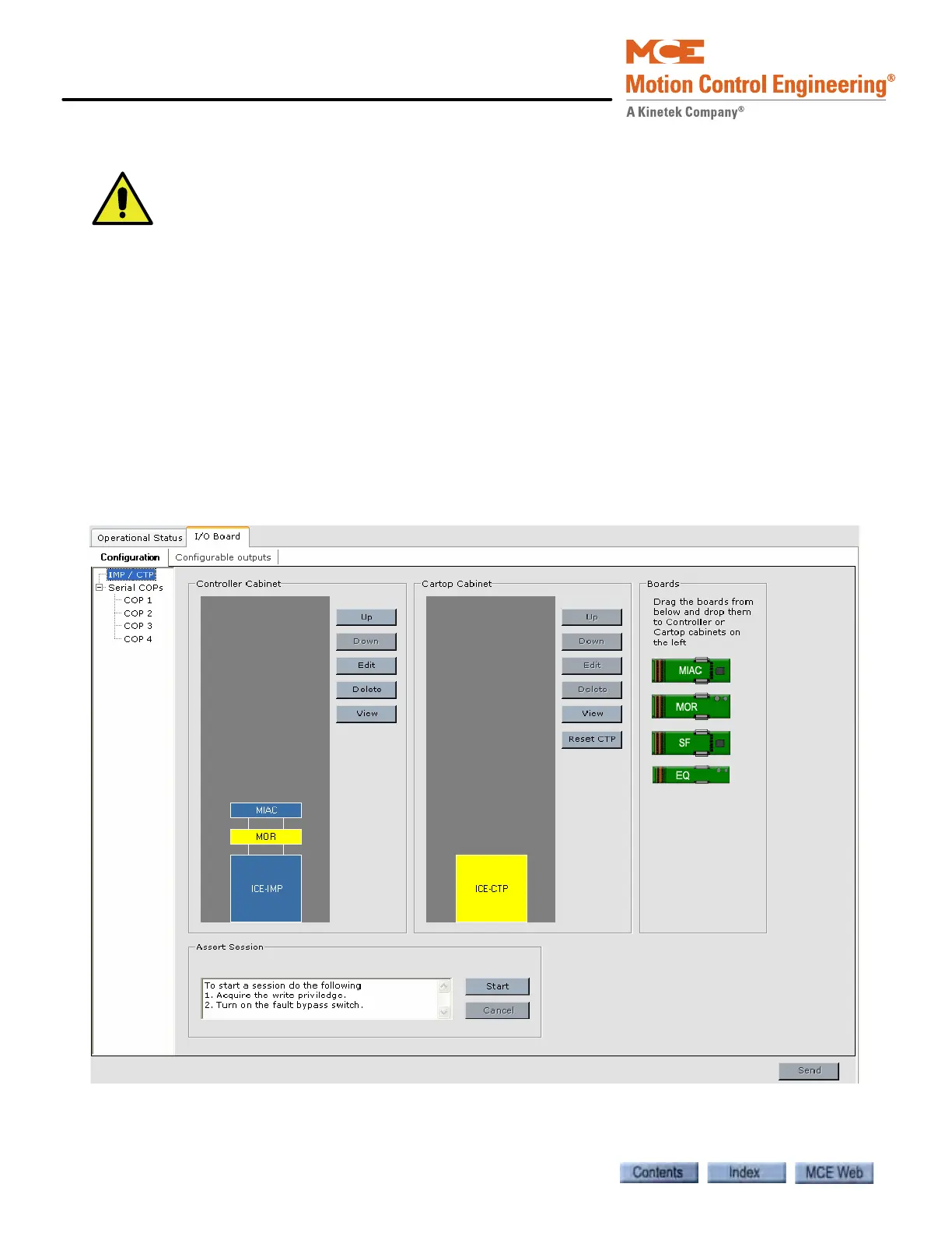
IMP / CTP In the window shown below (Configuration > I/O Boards > Configuration
tab), a Multiple Input AC (ICE-MIAC) board connected to the iBox Main Processor (ICE-IMP)
board is selected for editing. When the edit button is clicked, the Terminal Configuration (IMP -
MIAC) dialog, shown on the following page, is displayed.