DC Hoist Motor, Brake, and Encoder/Tachometer
2-23
2
iControl DC
Wiring the Brake
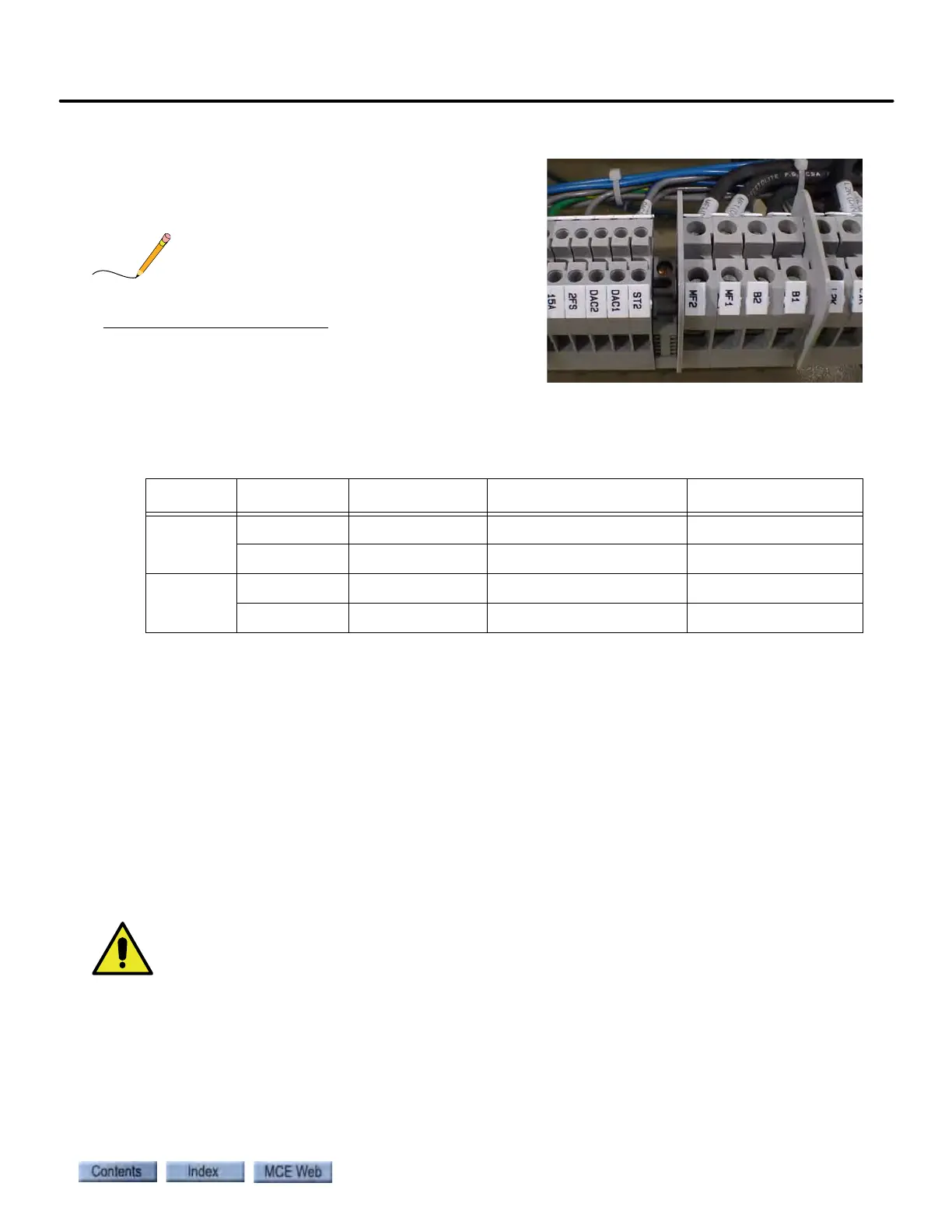
• Refer to job print drawing D2. Connect brake
wires to terminals B1 and B2 located just below
the iPower box.
Brake wires must not be routed in the same conduit
with DC motor wires or velocity encoder wires.
Tachometer or Encoder Installation and Wiring
A tachometer or a velocity encoder may be used.
Tachometer
(If you are using a velocity encoder, please see the next topic.) When installing a tachometer, do
not mount it near a magnetic field (for example, the motor field coils). Magnetic fields may
cause the tachometer to report incorrect speeds. Note also that any vibration caused by the
tachometer cannot be corrected inside the drive. The tachometer wheel and the surface on
which it runs must be smooth and the tachometer must be mounted so that it can maintain con-
tact without binding or bouncing.
Alignment of the tachometer coupling is extremely important. Most vibration problems are
caused by the tachometer or the way in which it was mounted. The tachometer mounting must
be rigid and the tachometer wheel must be aligned precisely with the surface it is running on
(i.e., the brake drum or drive sheave).
In geared applications, do not drive the tachometer from the sheave because gear lash cannot be
compensated by the drive unit.
Table 2.3 Selecting a Tachometer or a Velocity Encoder
Machine Device Shaft Mounting Brake Drum Mounting Sheave Mounting
Geared Tachometer Yes No No
Encoder Yes 1024PPR No No
Gearless Tachometer No Yes Yes
Encoder Yes 12,700PPR Yes 1024PPR Yes 1024PPR