iBox Field Connections
11-7
11
iControl DC
iBox Field Connections
The majority of field connections to the iBox are made through plugable terminal strips along
the left edge of the iBox (as you face it). Field connections are control and data connections to
and from equipment external to the iBox. For example, connections through the traveler cable
to car and hoistway equipment or connections to additional machine room equipment like rope
grippers, velocity encoders, governors, etc. In this section, three tables describe connections —
iBox connections, expansion board connections, and iControl terminal connections respec-
tively.+--+Controller Terminal Field Connections
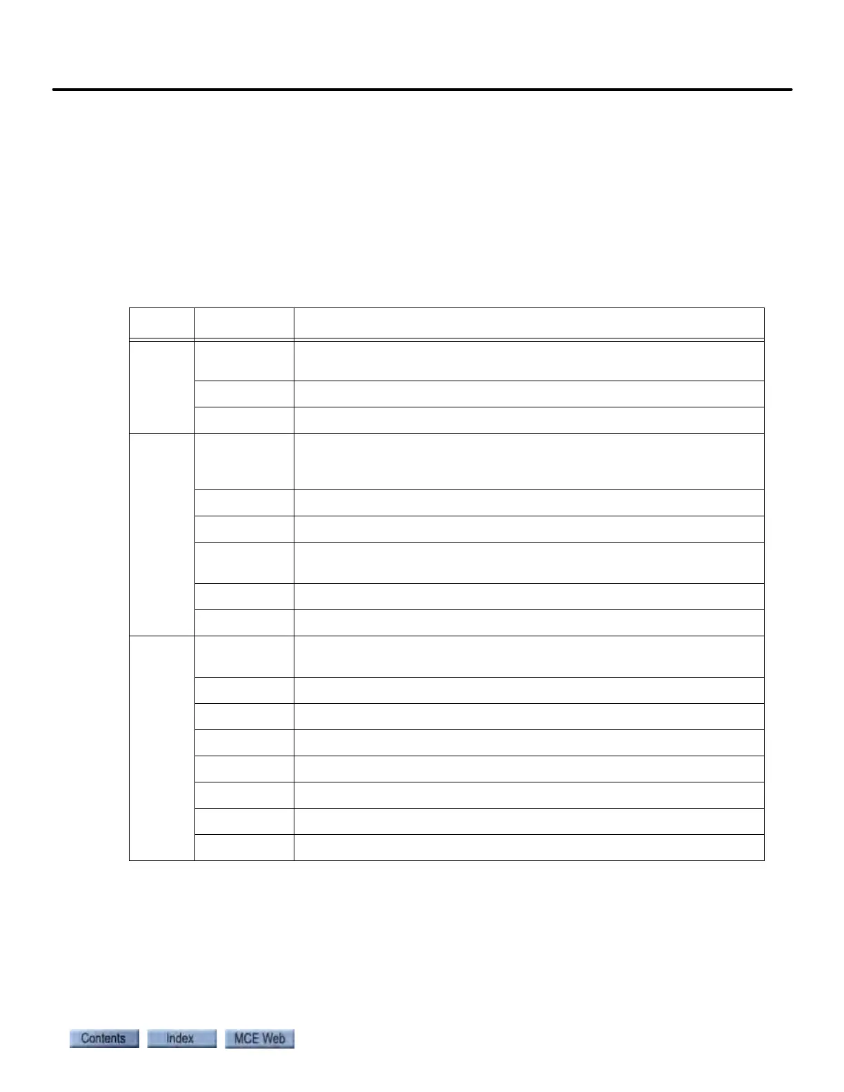
Table 11.3 iBox Field Connections
Source Connection Signal Description
TACH
TS Tach positive signal. Analog. 0 - 30 VDC (15 VDC @ 1000 RPM). Please
refer to “Tachometer or Encoder Installation and Wiring” on page 2-23.
TC Tach common (negative in respect to TS when car moving down)
SHLD Tach shield connection (connect at iBox-end only)
POSITION
DP1+ Positive going, +15V, digital pulse stream from iLand to iLink to iBox
(DP1 leads DP2 when car moves up). Please refer to “iLand Landing Sys-
tem” on page 3-2.
DP1- Negative going, -15V, digital pulse stream from iLand to iLink to iBox.
SHLD Shield connection for twisted-pair DP1+/DP1-
DP2+ Positive going, +15V, digital pulse stream from iLand to iLink to iBox
(DP2 leads DP1 when car moves down)
DP2- Negative going, -15V, digital pulse stream from iLand to iLink to iBox
SHLD Shield connection for twisted-pair DP2+/DP2-
VELOCITY ENCODER
A+ Positive going, +12V, digital pulse from motor velocity encoder. Please
refer to “Tachometer or Encoder Installation and Wiring” on page 2-23.
A- Negative going, -12V, digital pulse from motor velocity encoder.
B+ Positive going, +12V, digital pulse from motor velocity encoder.
B- Negative going, -12V, digital pulse from motor velocity encoder.
Z+ Positive going, +12V, digital pulse from motor velocity encoder.
Z- Negative going, -12V, digital pulse from motor velocity encoder.
VE- Encoder power return
VE+ +12 VDC power to encoder (relative to VE-)