Troubleshooting
6-118 Manual # 42-02-7223
System 12 SCR Drive
This section provides a quick reference to the indicators, test points and jumper settings found
on the SCR-LGA Drive Logic board and explains how to replace various components in the Sys-
tem 12 SCR Drive, including:
•Replacing Fuses
• Replacing Contactors
• Replacing SCRs and Diodes
•Replacing PC Boards
SCR-LGA - SCR Drive Logic Board Quick Reference
This quick reference provides descriptions of the following:
• Indicators on the SCR-LGD and SCR-LGA boards
•SCR-LGA Test Points
• SCR-LGA Jumper Settings
Refer to the SCR-LGA Board Layout to locate the jumpers and test points.
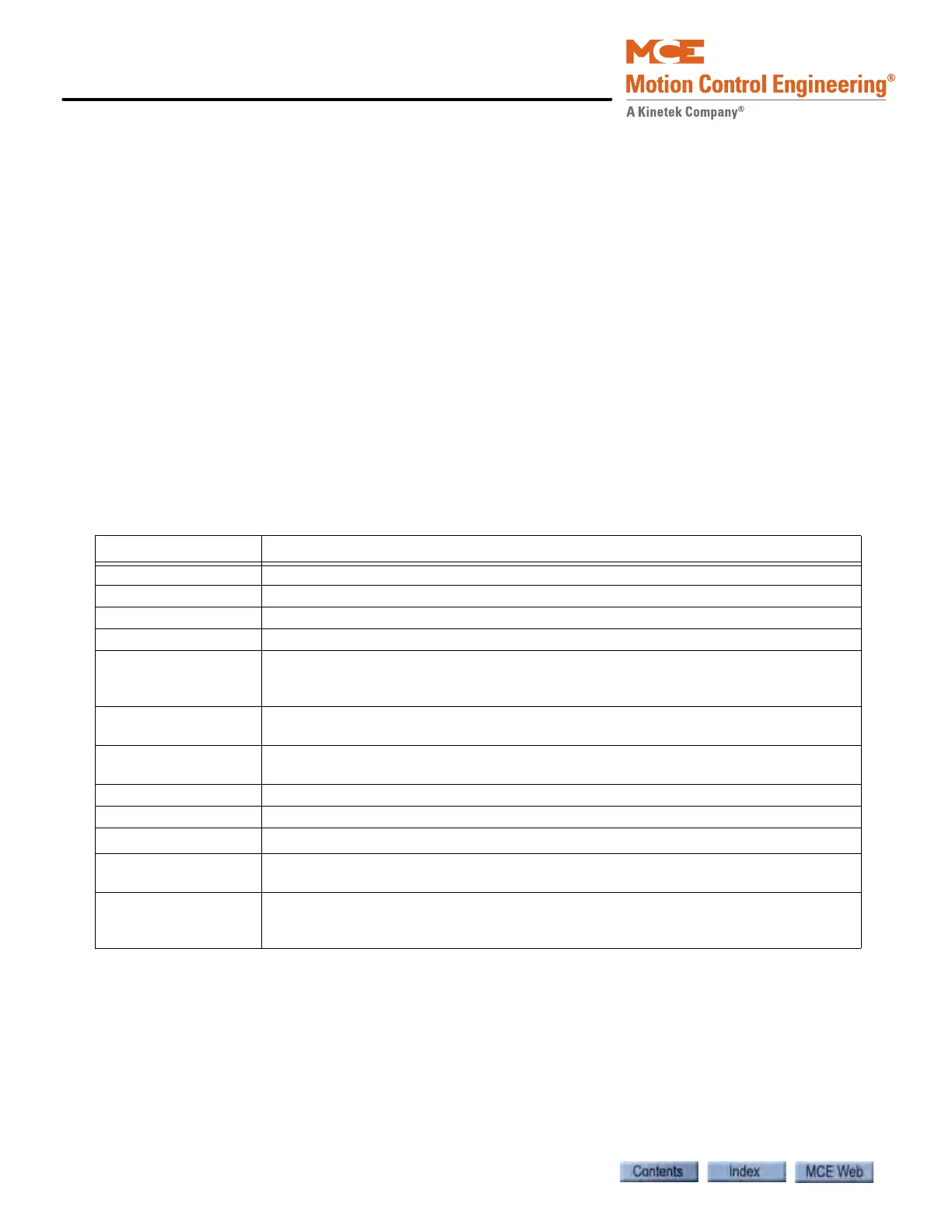
Table 6.29 Indicators on the SCR-LGD and SCR-LGA Boards
Indicator Description
Up Direction Up direction is selected.
Down Direction Down direction is selected.
Drive Ready There are no faults and the drive is ready to run.
Drive ON The drive is enabled and is producing torque output.
Current Limit
The drive has reached either the current or voltage limit set by the drive header and
software parameters Armature current limit or Armature voltage limit (Configuration
> Safety tab).
Low Line - WYE
Secondary
The voltage at the Wye connection of the drive isolation transformer secondary is
below 30% of the rated value.
Low Line - Delta Sec-
ondary
The voltage at the Delta connection of the drive isolation transformer secondary is
below 30% of the rated value.
WYE P.R. The phase relationship of the Wye connection (Y1, Y2, Y3) is incorrect.
Delta P.R. The phase relationship of the Delta connection (X1, X2, X3) is incorrect.
30
0
P.R.
The phase relationship between the Wye and Delta connections is incorrect.
Contactor or High Cur-
rent Fuse Failure
The main contactor is not picked, or one or more of the high current fuses is open
when the drive is enabled.
PLL No Lock
(SCR-LGA board) The PLL circuit has a problem of synchronization with the Delta
connection from the AC line. This indicator will also turn on while the controller is
powering up and when the SCR-LGA board is being reset.
 Loading...