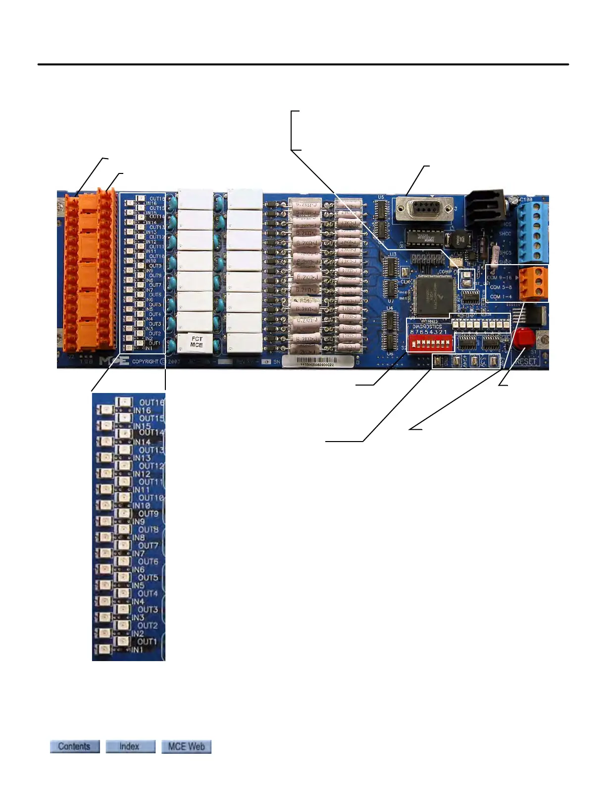
EasyManuals Logo

MCE iControl User Manual

Default Icon
806 pages
To Next Page IconTo Next Page
To Previous Page IconTo Previous Page
Page #391 background imageLoading...
Page #391 background image
iControl Circuit Board Quick References
6-117
6
iControl DC
Figure 6.19 SC-ION Serial Control I/O Board
Board
Reset
Inputs
Outputs
High/Low (Current Source/
Current Sink) Output Selec-
tion (J4). For example, con-
necting the COM 9 - 16
terminal to the MCE #1
(common) bus would mean
that when one of outputs 9
through 16 was active the
signal connected to it would
be taken to ground (sink/
active low).
DIP switch and LEDs used
in factory diagnostics and
programming. No field
application.
Testpoints
,
Ground
+24V
+3.3V
LED lights when corresponding
input or output is active.
Board programming port:
Factory use only.
COMP ON:
On = Computer on
Off = Computer resetting
RST_OUT: Low when computer is in reset mode

Table of Contents

Questions and Answers:

Question and Answer IconNeed help?

Do you have a question about the MCE iControl and is the answer not in the manual?

MCE iControl Specifications

General IconGeneral
BrandMCE
ModeliControl
CategoryController
LanguageEnglish