System 12 SCR Drive
6-119
6
iControl DC
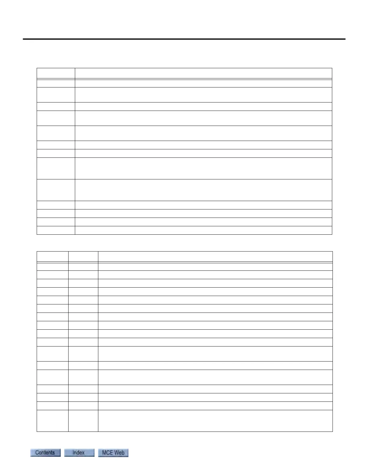
Table 6.30 SCR-LGA Board Test Points
Test Point Description
FA Firing Angle: ‘+’ = not firing, ‘-’ = firing (-6VDC = maximum output)
IZO Integrator Reset Status: Used to adjust the zero offset for the Current Loop Integrator or the
Voltage Loop Integrator.
TP1 Armature Differential: Hoist motor armature voltage = TPI volts x 100.
TP2 Armature Voltage (scaled): 10VDC = 100% of Drive armature voltage rating. Actual armature
voltage = Drive voltage rating x voltage at TP2 I 10 volts.
TP3 Armature Current (scaled): Measured in volts, 1.8 volts = 100% of Drive armature current
rating. Actual armature current = Drive current rating x voltage at TP3 I 1.8 volts.
TP3F Pure DC Armature Current: 1.8 volts = 100% of Drive current rating.
TP4 Line Frequency: Sine wave with frequency = line frequency (50 Hz or greater).
TP5 Direction of Current Flow: When drive is enabled, +15VDC = current flow from A2 to A1 and
0 VDC = current flow from A1 to A2. When drive is disabled, test point indicates previous
direction of armature current flow.
TP6 Current Loop integrator Output: 0.0 VDC when drive is disabled. Voltage at TP6 should not
drift when the Pattern scaling parameter (Configuration > Pattern > Common tab) = 0 and
the drive is enabled.
TP17 Burst Enable: 720 Hz square wave with on-time of 300 microseconds A10%.
TP18 Total Current Command: measured in volts.
TP19 Fault Bus: 15 VDC = normal, 0 VDC = fault condition in the SCR drive.
TP20 Drive reset: 0.0 VDC = normal (Ready is ON), -15 VDC = drive is being reset.
Table 6.31 SCR-LGA Board Jumper Settings for use with iControl
Jumper Setting Description
JP1 N/C (Header U81) Function not used.
JP2 N/C (Header U81) Function not used.
JP3 B (Header U81) B = Current Loop selected.
JP4 A (Header U81) Permanently soldered jumpers
JP5 B If JP2 is not selected, JP5 can be set to either A or B.
JP6 ON On = Continuous/Discontinuous Detection circuit selected.
JP7 A A = Low gain for current loop. B = High gain for current loop.
JP8 ON ON = Auto-tune for Current Loop Offset selected.
JP9 ON Must be set the same as JP8.
JP10 ON ON = Auto-tune for Current Sensor Offset selected.
JP11 A
A = Current balancing selected for more current in WYE.
B = Current balancing selected for more current in DELTA.
JP12 N/C N/C = Normal operation. Always use N/C setting for iControl.
JP13 A
A = Current balancing selected for more current in WYE.
B = Current balancing selected for more current in DELTA.
JP14 N/C N/C = 60Hz AC. ON = 50Hz AC.
JP15 A A = iControl setting.
JP16 A A = iControl setting.
JP17 A A = iControl setting. Loss of power at the Emergency Power Input causes a signal to
be sent to the drive which causes the drive to modify the PLL feedback gain so that
the PLL circuit can tolerate frequency shift for faster response.