Controller Cabinet Installation
2-13
2
iControl DC
Input/Output Terminals Input/Output assignment may be changed in the iView
application but, the job prints specify, and the system is shipped supporting, a logical configura-
tion. For example, the #1 floor button in the car operating panel is connected to the #1 input to
the cartop ICE-MIAC board. When the button is pressed, the input signal directs the controller
to register a call to floor #1 and the controller activates the #1 output on the cartop ICE-MOR
board. The active output completes a circuit and the lamp in the #1 button is lighted so that the
passenger knows the call has been registered.
The correlation between input and output is assigned at the factory according to the job survey
and the correct wiring is stipulated on the job prints. It is imperative that, if any changes or
additions are made, MCE be contacted so that the job prints may be updated to reflect current
connections.
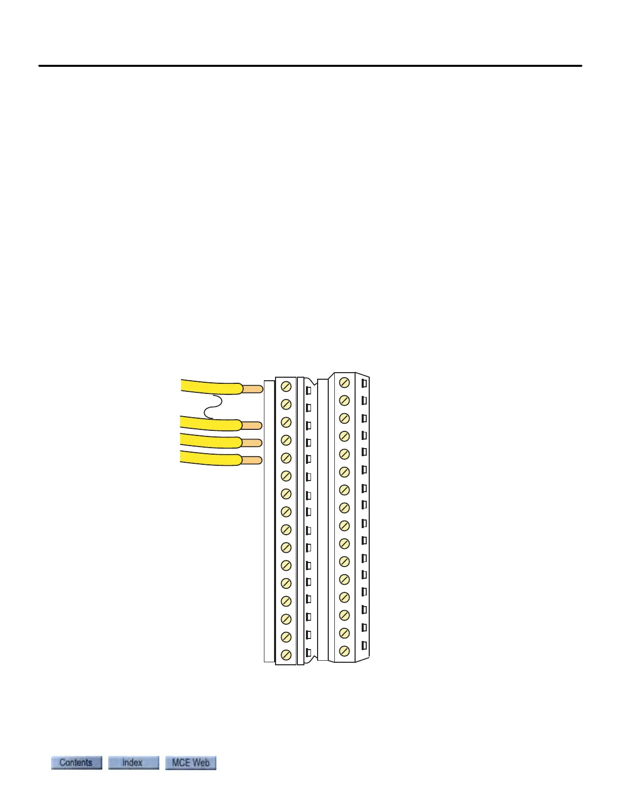
Input/Output Wiring Inputs and outputs are wired to pluggable terminals on the car-
top or controller ICE-MIAC (inputs) and ICE-MOR (outputs) boards. The connector numbering
is the same on input and output boards. Terminal arrangement is shown in the illustration
below.
Figure 2.4 ICE-MIAC and ICE-MOR Connector Assignments