System Options
5-34 Manual # 42-02-7223
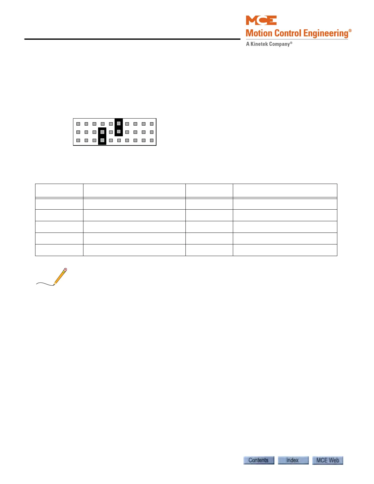
• Call Type Jumper
Jumper JP1 sets the call type for the two switch/lamp combinations serviced by the node board
(or the individual jumpers can be thought of as setting the last digits of the boards two unique
serial addresses). You set one jumper for each of the boards two I/Os. The most common setting
for JP1 jumpers, Down Front and Up Front hall calls, is shown in the following illustration. The
table after the illustration lists all call types.
Only the Sub-address jumper, JP1, can have more than one jumper inserted. (It can have a max-
imum of two — one to complete the DN address, the other to complete the UP address.) All
other node board jumpers can have ONLY ONE jumper inserted. If more than one jumper is
inserted in JP2 or JP3, the system will not work.
Wiring the Nodes Each serial bus consists of a twisted pair of wires, one orange and
one blue. Each “node” on the bus (i.e., a hall call button/lantern pair), has a connection to the
orange wire and a connection to the blue wire in addition to button and indicator lamp connec-
tions. See the job prints and instructions accompanying the hall call kits for details.
Table 5.2 Floor Sub-Addresses (Call Type) Jumper Settings
Sub-Address Default Definition Sub-Address Default Definition
0 Front Auxiliary Down Call 5 Standard Rear Down Call
1 Rear Auxiliary Down Call 6 Standard Front Up Call (shown)
2 Front Auxiliary Up Call 7 Standard Rear Up Call
3 Rear Auxiliary Up Call 8 Commandeer Front Call
4 Standard Front Down Call (shown) 9 Commandeer Rear Call