Serial Hall Call
5-45
5
iControl DC
Driver Voltages Test The hall call driver can be more thoroughly tested if necessary.
The test is relatively simple on iCentral units shipped after July, 2005 because a female, “test”
connector has been installed in the middle of the ribbon cable connecting the driver to the SC-
HCE (Digi board) assembly. Earlier units do not have the test connector.
Note: Digi-board connector ground pins are 2,3,4,6,9,11,12,13,14,15, and 17.
1. Cut three pieces of 22 AWG solid wire 2” in length. Strip ½” insulation off each end.
These will be used as “jumpers” and test probes during the test.
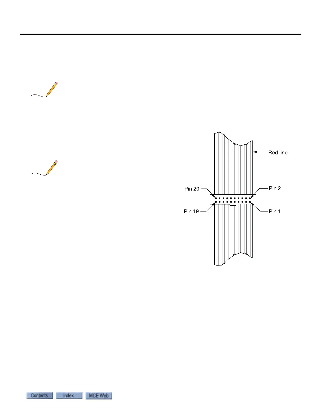
2. At the SC-HCE board end, disconnect the
ribbon cable connected to the hall call
driver. Note the test connector in the middle
of the cable. Its pinout is as shown.
Alternatively, if the cable does not have a test con-
nector, insert a 20 conductor ribbon cable, with a
female connector at each end, into the SCHCD J2
socket.
3. Remove orange and blue bus wires from the
hall call driver bus terminal connector.
4. Connect 120 VAC power to Serial Hall Call
Driver power input terminals.
5. Insert the negative DC voltmeter lead to the
Hall Call Bus SHCC Terminal connector.
• Driver DC power supply test
1. Insert a wire test probe into pin 19. Connect the positive voltmeter lead.
2. You should see 42-volts (+/- 10%). Remove the wire probe.
• Digi-board DC power supply test
1. Connect the positive voltmeter probe/lead to pin 8.
2. You should see 10-volts (+/- 10%).