System Options
5-66 Manual # 42-02-7223
Adjust the Amplifier
1. Before adjusting the sensor amplifier the following conditions must first be met:
• Power to the controller
• The car is on Inspection operation
• The brake is already adjusted to hold 125% of full load
• Car positioned level with floor, doors open, so test weights may be added and removed
2. With the car empty, adjust the clearance between sensor and target so that 0.3 to
1.0VDC is present between test points LW+ to LW- on the iLink CTP board. This is a
sensitive apparatus, so hold the target while loosening the adjustment bolts of the tar-
get, make the adjustment, and tighten the bolts. (Increasing the distance between the
target and the sensor increases the voltage; decreasing distance decreases the voltage.)
3. Remove all personnel from the pit (in case the car moves when fully loaded) and put
100% of load in the car.
4. Set the LW ADJ trimpot on the CTP (cartop) board fully clockwise and check that there
is LESS THAN 14VDC between test points TP LW and GND.
5. Adjust the LW ADJ trimpot so that there is no more than 8VDC and no less than 4VDC
between TP LW and GND (8VDC recommended).
Verify Performance
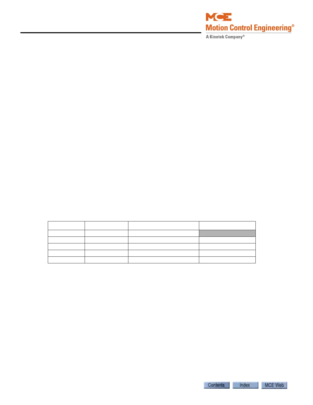
1. Check the voltages measured between test points LW+ and LW- with the following
loads. This information is used to verify rubber pad resilience for the isolation platform.
Document the data below.
The variation between voltage increase entries should be linear. If voltage increase is more than
25% different from the entry just above it, check the following:
• Condition of rubber pads
• Voltage variance when weight is in center of car vs. on edge of car (sagging problem)
Adjust iControl Parameters The load weigher is now installed and properly
adjusted. However, the parameter adjustments for the load weigher must be completed. Please
refer to “Load Weigher Configuration” on page 4-38.
Recommended Maintenance
Once a month, check the voltage between LW+ and
LW-. It should be within 0.3V and 1.0VDC when the car is empty. If the voltage is outside
the 0.3 to 1.0VDC range, adjust the target bracket.
Additionally, periodic checks of the voltage increase with varying load conditions will help diag-
nose when the rubber pads begin to lose elasticity.
Table 5.10 Verify MCE Load Weigher Performance
Load in pounds Volts across LW+ to LW- Voltage increase
No load (1)
1/4 of full load (2) (2)-(1)
½ of full load (3) (3)-(2)
3/4 of full load (4)
(4)-(3)
Full load (5)
(5)-(4)