Troubleshooting
6-86 Manual # 42-02-7223
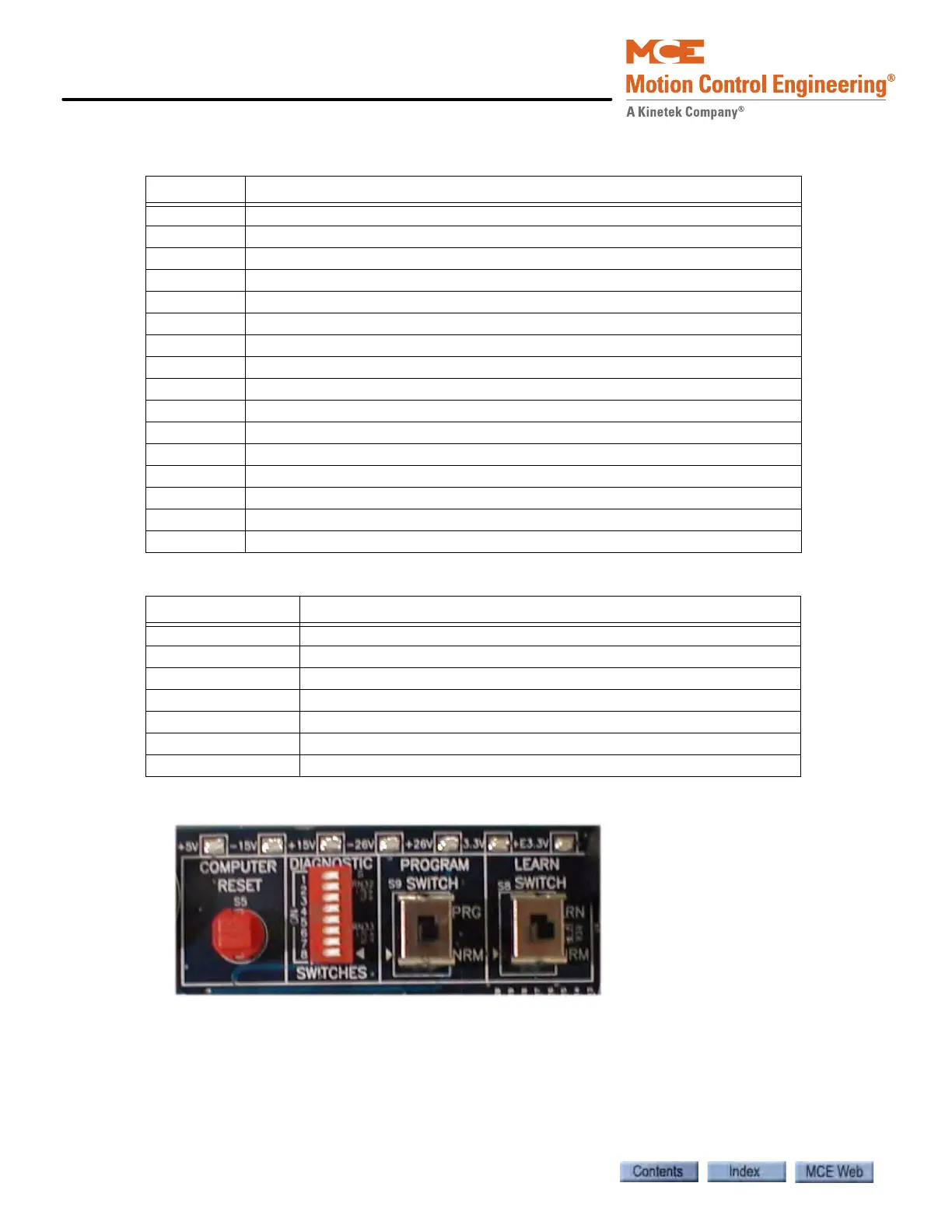
Figure 6.4 ICE-CTP Board Switches
• Computer Reset: Press to initialize the Cartop Processor board computer.
• Diagnostic Switches: Factory board test use only.
• Program Switch: Used at the factory during board programming.
• Learn Switch: Used at the factory during board programming.
• Test points: +5V, -15V, +15V, -26V, +26V, +3.3V, +E3.3V (emergency logic power pro-
vided by on board battery).
Table 6.7 ICE-CTP Board Connections
Terminal Description
SHLD Shield: Common
26V 26V output to load weigher
LW- Input from Load Weigher (analog voltage)
LW+ Input from Load Weigher (analog voltage)
DP2- Position input from iLand (balanced pair with DP2+)
DP2+ Position input from iLand (balanced pair with DP2-)
SHLD Shield: Common
DP1- Position input from iLand (balanced pair with DP1+)
DP1+ Position input from iLand (balanced pair with DP1-)
SHLD Shield: Common
TX+ Transmit to iBox (connect to iBox terminal RX+)
TX- Transmit to iBox (connect to iBox terminal RX-)
SHLD Shield: Common
RX+ Receive from iBox (connect to iBox terminal TX+)
RX- Receive from iBox (connect to iBox terminal TX-)
SHLD Shield: Common
Table 6.8 ICE-CTP Board Testpoints
Test point State
GND (x4) Ground test points
Volt (x8) +2.5, +3.3, +5, -15V, +15V, -26V, +26V
LW Measured from LW to TP_LW, 0.3 — 1.0 VDC = Empty car.
LW- Measured from LW- to TP_L@, -0.3 — -1.0 VDC = Empty car.
TP_LW Measured from TP_LW to GND, 4 — 8 VDC = Full car.
RSTOUT 0V= computer reset
CLKOUT 33MHz microprocessor clock