iControl Circuit Board Quick References
6-109
6
iControl DC
.
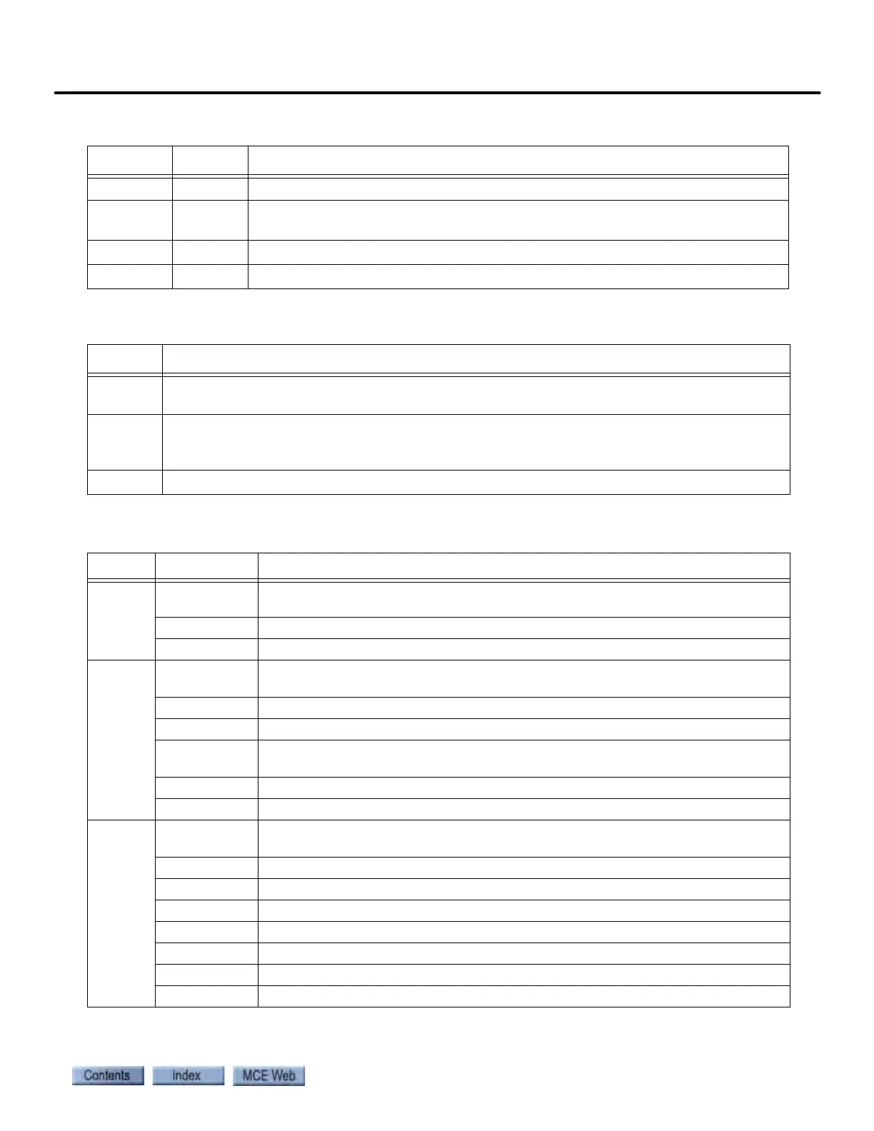
Table 6.24 ICE-SAF Board Jumper Table
Jumper Setting Description
JP1 A Encoder Voltage. A = +5V, B = +15V
JP3 AC Pre-Torque Filter (AC / DC): AC setting is hard wired, adds filtering to the pre-
torque output.
JP5 B Tach input range. A = 20-80V, B = 81-190V
JP6 B Tach input range. A = 20-80V, B = 81-190V
Table 6.25 ICE-SAF Board Switches
Switch Description
SW1 Serial Port switch: Setting for the Drive Serial Port (AC Drive / DC Drive). DC Drive setting
hard wired.
SW2 Encoder / Tach:
Encoder = AC drive with velocity encoder connected to AC drive.
Tach = DC drive or AC drive with velocity encoder connected to iBox VELOCITY inputs.
SW4 DCC Filter (ON / OFF) Default = ON, adds filtering to Drive Current Command output.
Table 6.26 iBox Field Connections on ICE-SAF Board
Source Connection Signal Description
TACH
TS Tach positive signal. Analog. 0 - 30 VDC (15 VDC @ 1000 RPM). Please refer to
“Tachometer or Encoder Installation and Wiring” on page 2-23.
TC Tach common (negative in respect to TS when car moving down)
SHLD Tach shield connection (connect at iBox-end only)
POSITION
DP1+ Positive going, +15V, digital pulse stream from iLand to iLink to iBox (DP1 leads
DP2 when car moves up). Please refer to “iLand Landing System” on page 3-2.
DP1- Negative going, -15V, digital pulse stream from iLand to iLink to iBox.
SHLD Shield connection for twisted-pair DP1+/DP1-
DP2+ Positive going, +15V, digital pulse stream from iLand to iLink to iBox (DP2 leads
DP1 when car moves down)
DP2- Negative going, -15V, digital pulse stream from iLand to iLink to iBox
SHLD Shield connection for twisted-pair DP2+/DP2-
VELOCITY ENCODER
A+ Positive going, +12V, digital pulse from motor velocity encoder. Please refer to
“Tachometer or Encoder Installation and Wiring” on page 2-23.
A- Negative going, -12V, digital pulse from motor velocity encoder.
B+ Positive going, +12V, digital pulse from motor velocity encoder.
B- Negative going, -12V, digital pulse from motor velocity encoder.
Z+ Positive going, +12V, digital pulse from motor velocity encoder.
Z- Negative going, -12V, digital pulse from motor velocity encoder.
VE- Encoder power return
VE+ +12 VDC power to encoder (relative to VE-)