iControl Circuit Board Quick References
6-111
6
iControl DC
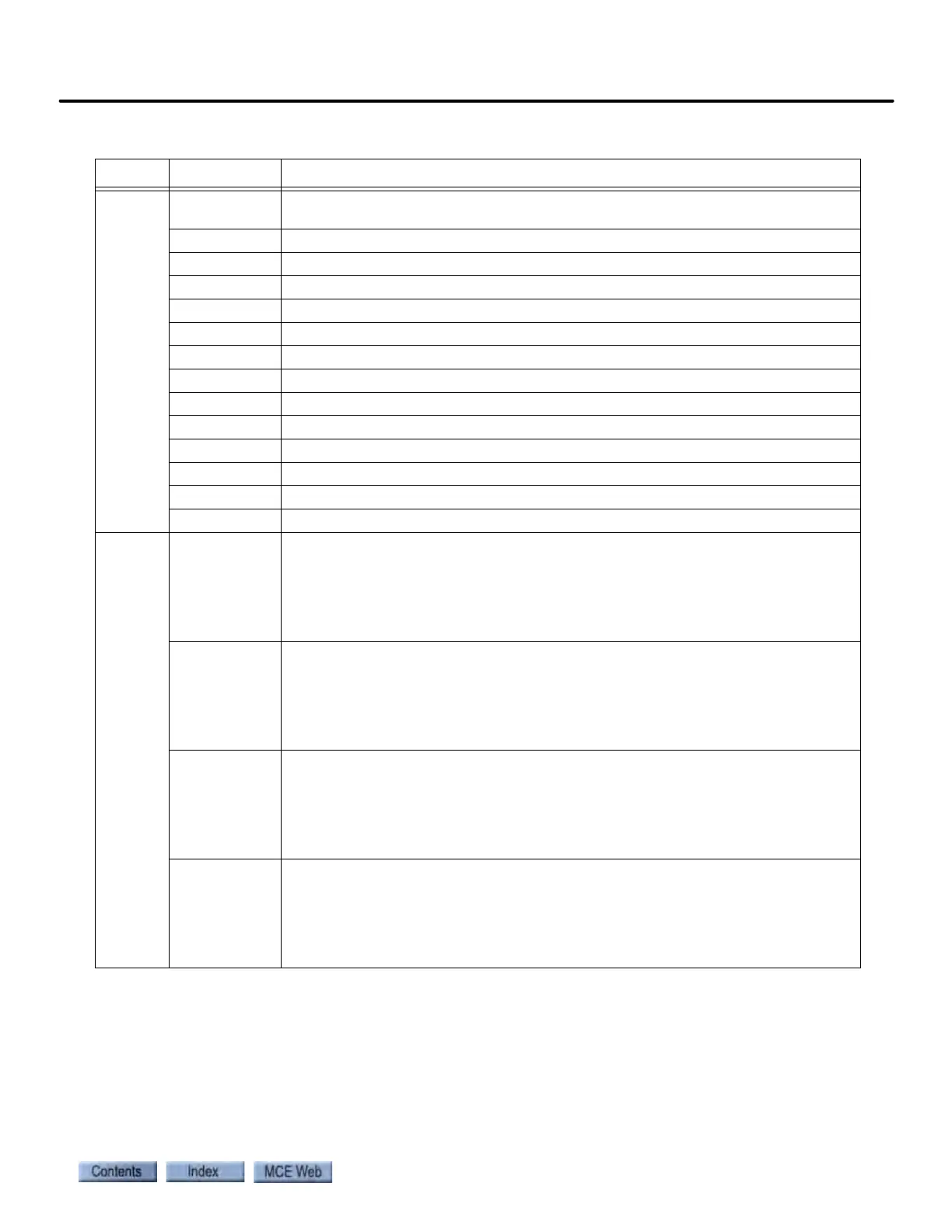
LIMITS
UNTD Up Normal Limit Direction switch input. 110 VDC = input on/switch closed. 0
VDC = input off/switch open.
UNT5 Up Slowdown Limit switch #5 input. (see UNTD)
UNT4 Up Slowdown Limit switch #4 input. (see UNTD)
UNT3 Up Slowdown Limit switch #3 input. (see UNTD)
UNT2 Up Slowdown Limit switch #2 input. (see UNTD)
UETS Up Emergency Terminal Limit switch input. (see UNTD)
UNT1 Up Slowdown Limit switch #1 input. (see UNTD)
DNT1 Down Slowdown Limit switch #1 input. (see UNTD)
DETS Down Emergency Terminal Limit switch input. (see UNTD)
DNT2 Down Slowdown Limit switch #2 input. (see UNTD)
DNT3 Down Slowdown Limit switch #3 input. (see UNTD)
DNT4 Down Slowdown Limit switch #4 input. (see UNTD)
DNT5 Down Slowdown Limit switch #5 input. (see UNTD)
DNTD Down Normal Limit Direction switch input. (see UNTD)
H/WAY
ATU Hoistway Access Top Up switch input. When the Car Panel Access Enable switch
(INA input) is on, an active input (key switch closure) here (110 VDC) will cause
the car to move up the hoistway. A hoistway limit switch electrically between
the ATU input and the activating switch will open and stop the car after it has
moved the required distance up the hoistway (if installed). Normal/Off state =
0 VDC. Refer also to the -MRW drawing in the job prints.
ATD Hoistway Access Top Down switch input. When the Car Panel Access Enable
switch (INA input) is on, an active input (key switch closure) here (110 VDC)
will cause the car to move down the hoistway. A hoistway limit switch electri-
cally between the ATD input and the activating switch will open and stop the car
after it has moved the required distance down the hoistway (if installed). Nor-
mal/Off state = 0 VDC. Refer also to the -MRW drawing in the job prints.
ABU Hoistway Access Bottom Up switch input. When the Car Panel Access Enable
switch (INA input) is on, an active input (key switch closure) here (110 VDC)
will cause the car to move up the hoistway. A hoistway limit switch electrically
between the ABU input and the activating switch will open and stop the car
after it has moved the required distance up the hoistway (if installed). Normal/
Off state = 0 VDC. Refer also to the -MRW drawing in the job prints.
ABD Hoistway Access Bottom Down switch input. When the Car Panel Access Enable
switch (INA input) is on, an active input (key switch closure) here (110 VDC)
will cause the car to move down the hoistway. A hoistway limit switch electri-
cally between the ABD input and the activating switch will open and stop the car
after it has moved the required distance down the hoistway (if installed). Nor-
mal/Off state = 0 VDC. Refer also to the -MRW drawing in the job prints.
Table 6.26 iBox Field Connections on ICE-SAF Board
Source Connection Signal Description