Troubleshooting
6-130 Manual # 42-02-7223
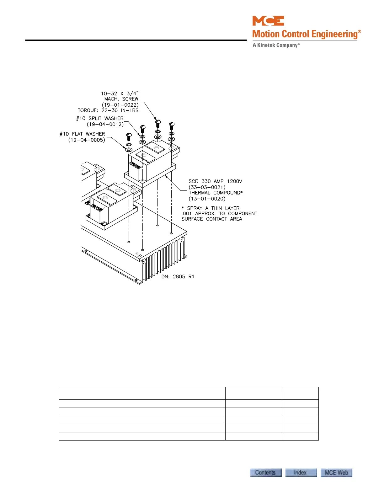
Replacing Direction Bridge (SCR7, SCR8) and Dynamic Braking (SCR9)
Ensure that all power is OFF at the main disconnect.
Figure 6.27 SCR7, SCR8, SCR9
1. Remove the bolts on terminals 1, 2, and 3 of the SCR being replaced. Place the bus bars
that connect to the SCR so that they will not obstruct removal and replacement.
2. Remove the SCR.
3. Clean the area where the SCR will be placed. Spray a thin layer (0.001 approximately) of
Thermal compound to the component surface contact area.
4. Install the SCR. Torque the mounting screws to 22–30 inch pounds.
5. Reconnect all wires and bus bars to the correct terminals. Torque bolts 1, 2, and 3 on the
SCR to 106–132 inch pounds.
Table 6.37 Replacement Parts for Direction Bridge and Dynamic Braking
ITEM (DESCRIPTION) MCE PART # UNIT
SCR (330 Amp 1200V SCR Pack) 33-03-0021 Each
Thermal Compound Spray - Non Silicone 13-01-0020 A/R
Mach. Screw (10-32 x 3/4" Mach. Screw) 19-01-0022 Each
Split Lock Washer (#10) 19-04-0012 Each
Flat washer (#10) 19-04-0005 Each