Drive Startup (System 12 SCR Drive)
2-51
2
iControl DC
2. Loosen the four captive screws securing the cover on the System 12 drive. Set the cover
aside.
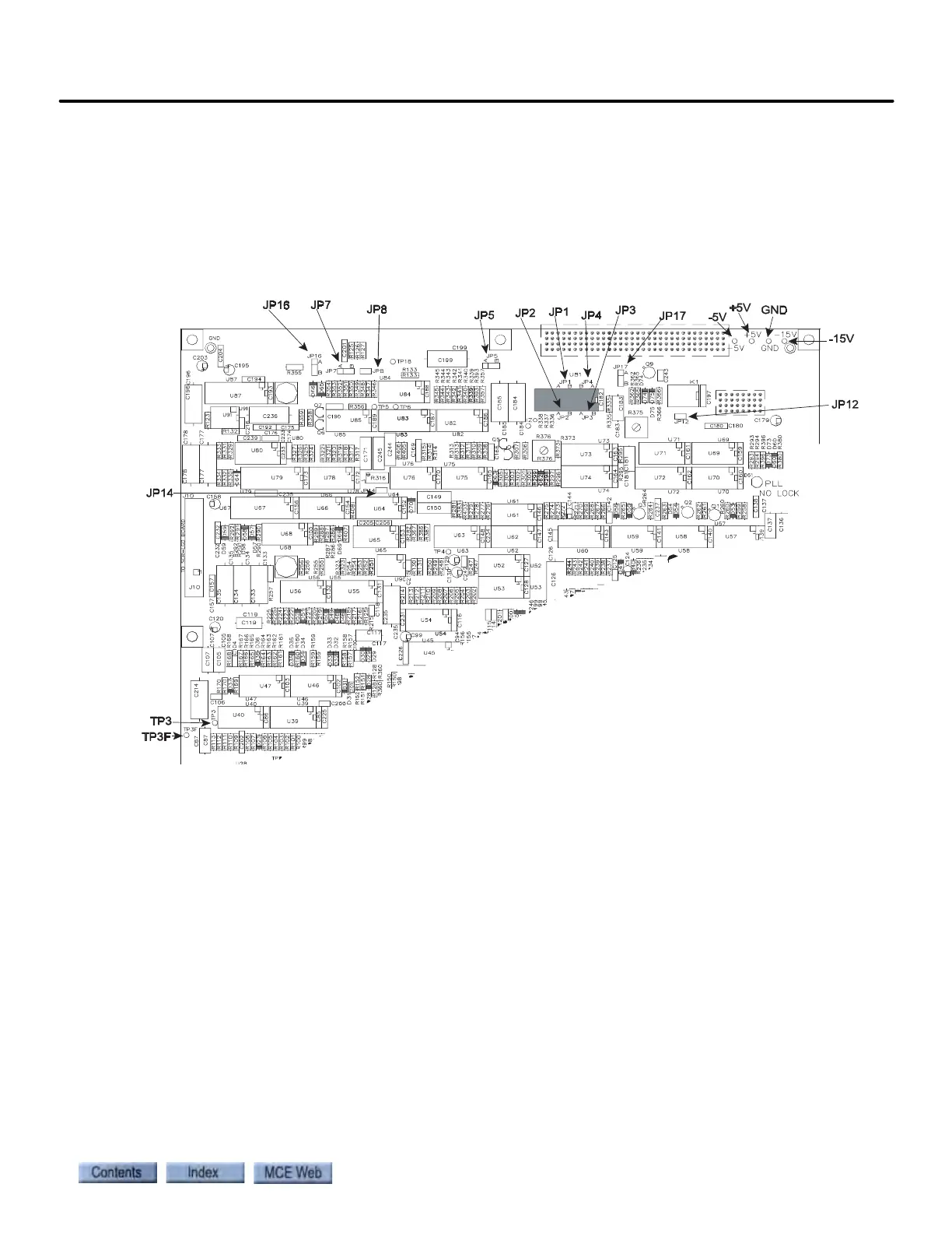
The SCR-LGA board is visible at the top left of the drive enclosure. (The LEDs visible through
the drive cover are mounted on a small PC board which is, in turn, mounted on the SCR-LGA
board.) Refer to the following illustration for the location of test points referenced in this proce-
dure.
Figure 2.14 System 12 Drive SCR-LGA Board Test Points
3. Output DAC: With the multimeter, measure between jumper JP3 and ground. If nec-
essary, adjust Output DAC on the iView screen until you measure as close to 0.0 volts as
possible (less than 1mV). (Remember to increment or decrement the iView setting, then
Send the value so the adjustment will take effect.)
4. Current loop integral: Use a multimeter to measure between jumper JP7 (‘A’ posi-
tion on jumper) and ground. If necessary, adjust Current loop integral on the Drive >
Calibration tab until you measure as close to 0.0 volts as possible (less than 1mV). (You
will need to increment or decrement the iView setting, then Send the value before the
adjustment will take effect.)
5. Current sensor: With the multimeter, measure between test point TP3F and ground.
If necessary, adjust Current sensor on the iView screen until you measure as close to 0.0
volts as possible (less than 1mV). (Remember to increment or decrement the iView set-
ting, then Send the value so the adjustment will take effect.)
6. Zero crossing: Note that the Zero crossing parameter is set to 0.0. This adjustment is
used only if zero crossing must be adjusted for ride quality reasons and the zero crossing
trim pot (R388 on the SCR-LGA board) does not allow sufficient adjustment. See the
following Note.