Phaser 7500 Printer Service Manual 2-77
Theory of Operation
Color Shift Detection
The keys for the color detection are the configuration of the MOB Sensor light
receptor and the shape ("<" shape) of the Regi Con patch image. This section
describes the principle of "Color Shift Detection" by using the example of Color
Shift between two colors.
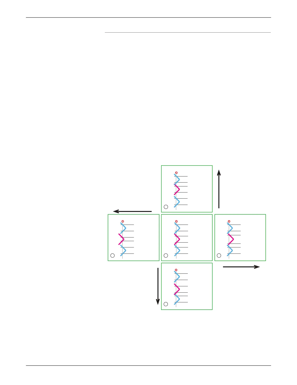
• (3) provides the ideal patch alignment where the Color Shift is zero. At this
time, the pulse output interval is tA1 to tA2 = tT1 to tT2 = tB1 to tB2 and tA2
to tT1 = tT2 to tB1.
• (2) and (4) provide the patch alignments where the Color Shift is only in the
fast scan direction. The pulse output intervals are each different compared to
(3), where the shift amount is 0.
• (1) and (5) provide the patch alignments where the Color Shift is only in the
slow scan direction. The pulse output intervals are each different compared to
(3), where the shift amount is 0.
Although the actual Color Shift occurs independently in both the fast scan and
slow scan directions and hence is a combination of items as shown in the following
illustration, the Color Shift between the two colors in the fast scan and slow scan
directions can be detected by using the difference of the patch pass timing in the
slow scan direction.
Shift in Fast
Scan Direction
Shift in Fast
Scan Direction
Shift in Slow
Scan Direction
Shift in Slow
Scan Direction
Sensor Vision
tA1
tA2
tB1
tB2
tT1
tT2
1
Sensor Vision
tA1
tA2
tB1
tB2
tT1
tT2
2
Sensor Vision
tA1
tA2
tB1
tB2
tT1
tT2
3
Sensor Vision
tA1
tA2
tB1
tB2
tT1
tT2
4
Sensor Vision
tA1
tA2
tB1
tB2
tT1
tT2
5
s7500-427

 Loading...


