Virtex-5 FPGA User Guide www.xilinx.com 127
UG190 (v5.0) June 19, 2009
Block RAM Port Signals
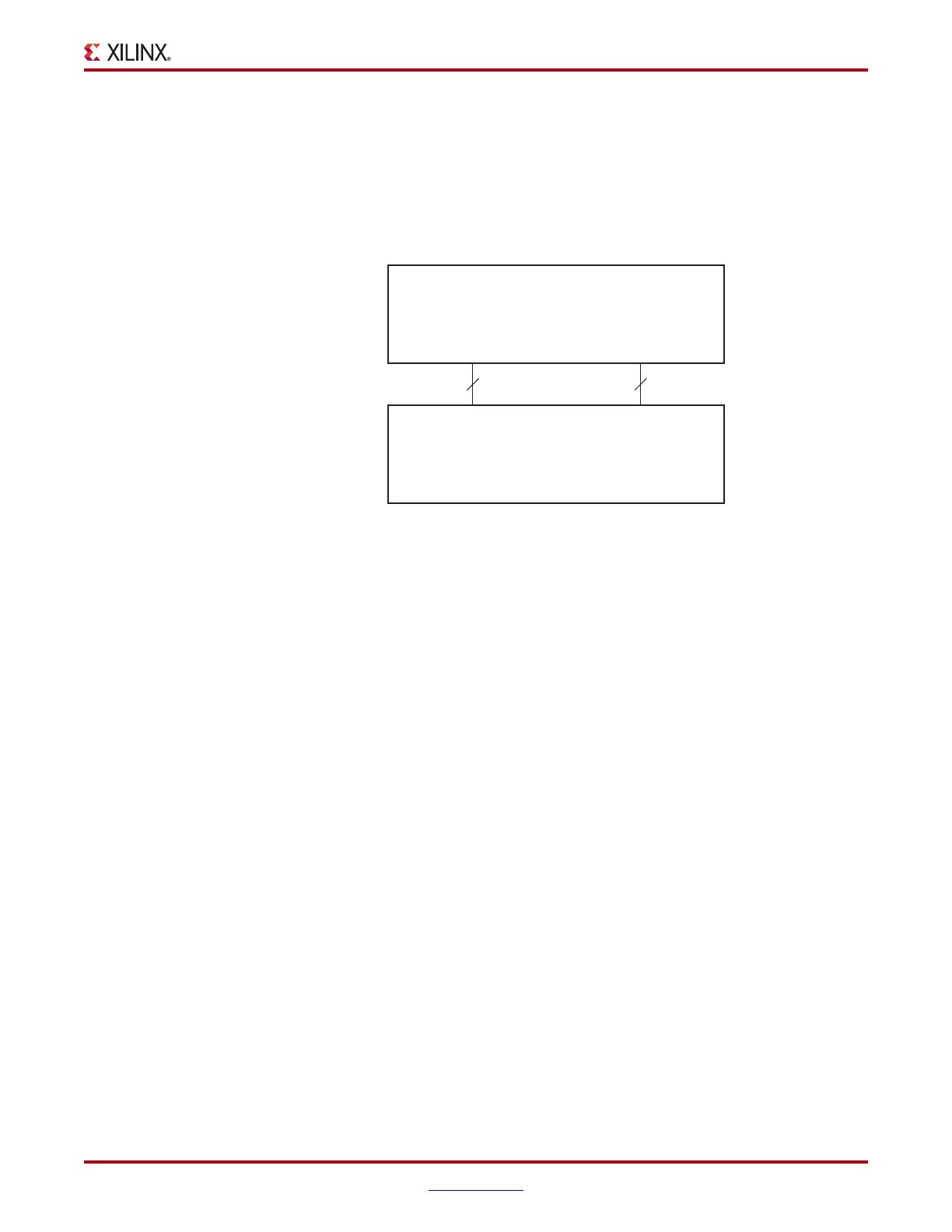
Cascade In - CASCADEINLAT[A|B] and CASCADEINREG[A|B]
The CASCADEIN pins are used to connect two block RAMs to form the 64K x 1 mode
(Figure 4-10.) This pin is used when the block RAM is the UPPER block RAM, and is
connected to the CASCADEOUT pins of the LOWER block RAM of the same port. When
cascade mode is not used, this pin does not need to be connected. Refer to the “Cascadable
Block RAM” for further information.
Cascade Out - CASCADEOUTLAT[A|B] and CASCADEOUTREG[A|B]
The CASCADEOUT pins are used to connect two block RAMs to form the 64K x 1 mode.
This pin is used when the block RAM is the LOWER block RAM, and is connected to the
CASCADEIN pins of the UPPER block RAM of the same port. When cascade mode is not
used, this pin does not need to be connected. Refer to the “Cascadable Block RAM” for
further information.
Inverting Control Pins
For each port, the six control pins (CLK, EN, and SSR) each have an individual inversion
option. EN and SSR control signals can be configured as active High or Low, and the clock
can be active on a rising or falling edge (active High on rising edge by default), without
requiring other logic resources.
GSR
The global set/reset (GSR) signal of a Virtex-5 device is an asynchronous global signal that
is active at the end of device configuration. The GSR can also restore the initial Virtex-5
device state at any time. The GSR signal initializes the output latches to the INIT (simple
dual port), or to the INIT_A and INIT_B value (true dual port.) See “Block RAM
Attributes.” A GSR signal has no impact on internal memory contents. Because it is a
global signal, the GSR has no input pin at the functional level (block RAM primitive).
Unused Inputs
Unused data and/or address inputs should be connected High.
X-Ref Target - Figure 4-10
Figure 4-10: Two RAMB36s Cascaded
ug190_4_12_040606
Upper
RAMB36
Lower
RAMB36
CASCADEINLATA/B CASCADEINREGA/B
CASCADEOUTLATA/B CASCADEOUTREGA/B
22
 Loading...


