Virtex-5 FPGA User Guide www.xilinx.com 339
UG190 (v5.0) June 19, 2009
Input/Output Delay Element (IODELAY)
IDELAYCTRL Timing
Table 7-12 shows the IDELAYCTRL switching characteristics.
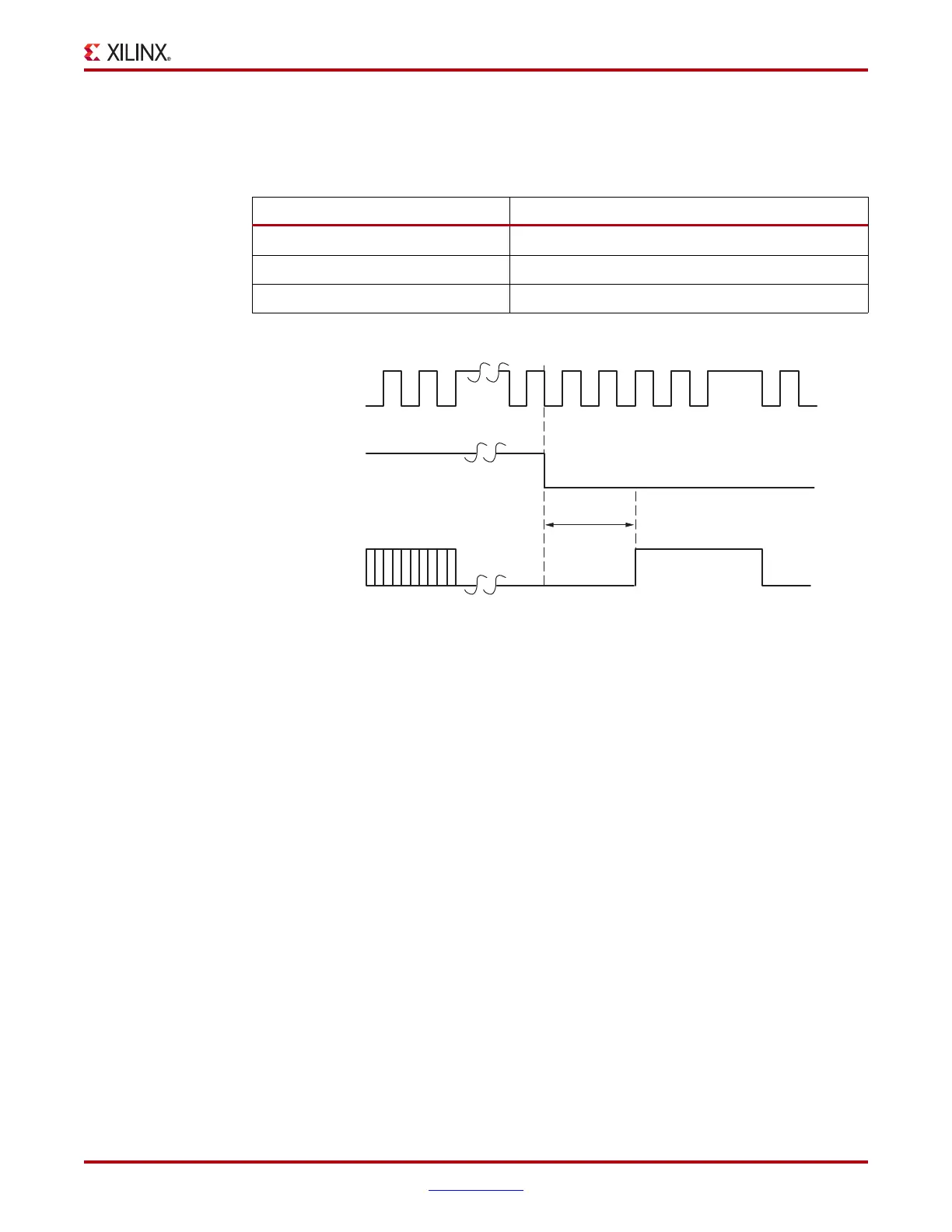
As shown in Figure 7-16, the Virtex-5 FPGA RST is an edge-triggered signal.
IDELAYCTRL Locations
IDELAYCTRL modules exist in every I/O column in every clock region. An IDELAYCTRL
module calibrates all the IDELAY modules within its clock region. See “Global and
Regional Clocks” in Chapter 1 for the definition of a clock region.
Figure 7-17 illustrates the relative locations of the IDELAYCTRL modules.
Table 7-12: IDELAYCTRL Switching Characteristics
Symbol Description
F
IDELAYCTRL_REF
REFCLK frequency
IDELAYCTRL_REF_PRECISION
REFCLK precision
T
IDELAYCTRLCO_RDY
Reset/Startup to Ready for IDELAYCTRL
X-Ref Target - Figure 7-16
Figure 7-16: Timing Relationship Between RST and RDY
RST
REFCLK
RDY
ug190_7_11_041206
T
IDELAYCTRLCO_RDY
 Loading...


