Virtex-5 FPGA User Guide www.xilinx.com 173
UG190 (v5.0) June 19, 2009
Chapter 5
Configurable Logic Blocks (CLBs)
CLB Overview
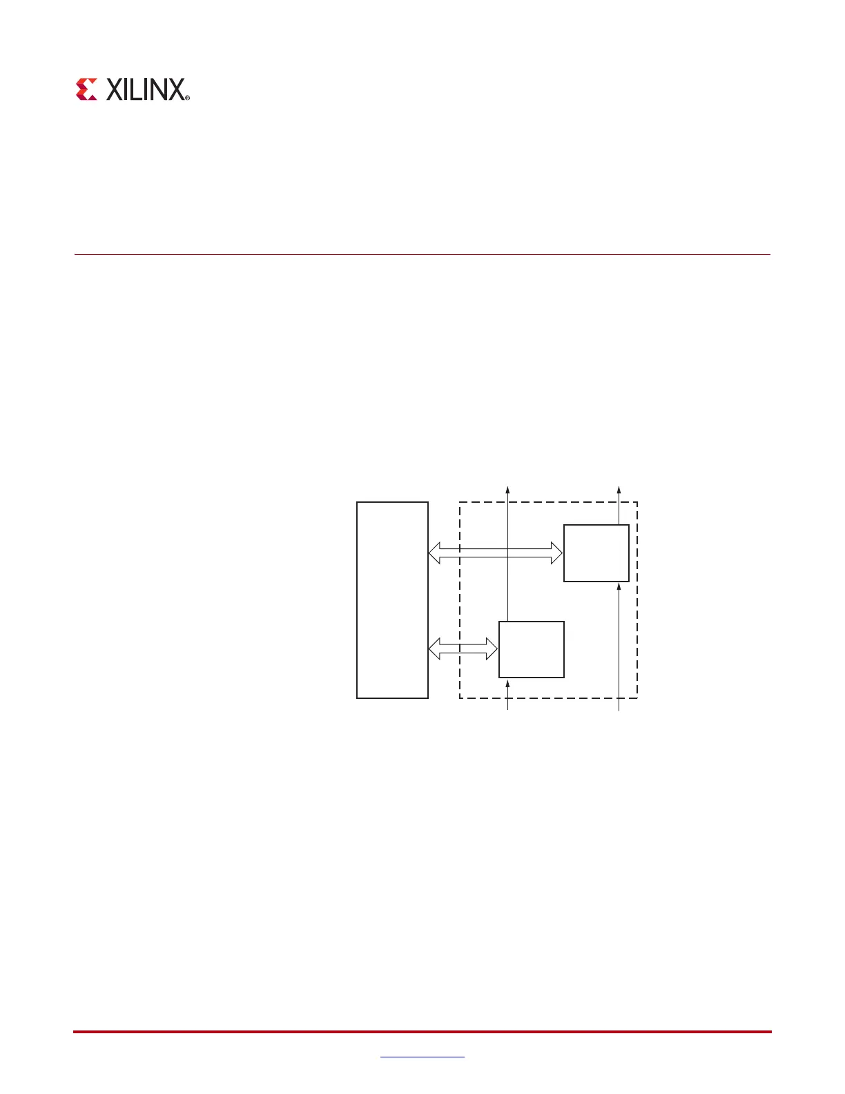
The Configurable Logic Blocks (CLBs) are the main logic resources for implementing
sequential as well as combinatorial circuits. Each CLB element is connected to a switch
matrix for access to the general routing matrix (shown in Figure 5-1). A CLB element
contains a pair of slices. These two slices do not have direct connections to each other, and
each slice is organized as a column. Each slice in a column has an independent carry chain.
For each CLB, slices in the bottom of the CLB are labeled as SLICE(0), and slices in the top
of the CLB are labeled as SLICE(1).
The Xilinx tools designate slices with the following definitions. An “X” followed by a
number identifies the position of each slice in a pair as well as the column position of the
slice. The “X” number counts slices starting from the bottom in sequence 0, 1 (the first CLB
column); 2, 3 (the second CLB column); etc. A “Y” followed by a number identifies a row of
slices. The number remains the same within a CLB, but counts up in sequence from one
CLB row to the next CLB row, starting from the bottom. Figure 5-2 shows four CLBs
located in the bottom-left corner of the die.
X-Ref Target - Figure 5-1
Figure 5-1: Arrangement of Slices within the CLB
Switch
Matrix
Slice(1)
COUTCOUT
CINCIN
Slice(0)
CLB
UG190_5_01_122605
 Loading...


