Virtex-5 FPGA User Guide www.xilinx.com 47
UG190 (v5.0) June 19, 2009
Chapter 2
Clock Management Technology
Clock Management Summary
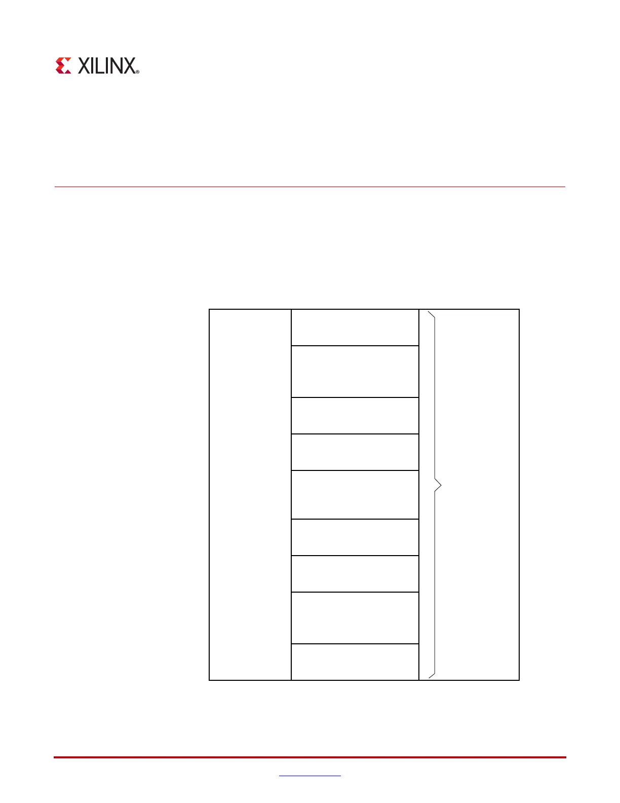
The Clock Management Tiles (CMTs) in the Virtex-5 family provide very flexible, high-
performance clocking. Each CMT contains two DCMs and one PLL. Figure 2-1 shows a
simplified view of the center column resources including the CMT block, where the DCM
is located. Each CMT block contains two DCMs and one PLL.
X-Ref Target - Figure 2-1
Figure 2-1: CMT Location
UG190_c2_01_022609
CMT Blocks
(Top Half DCMs/PLLs)
CMT Blocks
(Bottom Half DCMs/PLLs)
Clock I/O
(Top Half)
Clock I/O
(Bottom Half)
Config I/O
(Top Half)
Config I/O
(Bottom Half)
I/O Banks
(Larger Devices Only)
I/O Banks
(Larger Devices Only)
Virtex-5 FPGA
Center Column
Config Blocks and
BUFGs
 Loading...


