62 www.xilinx.com Virtex-5 FPGA User Guide
UG190 (v5.0) June 19, 2009
Chapter 2: Clock Management Technology
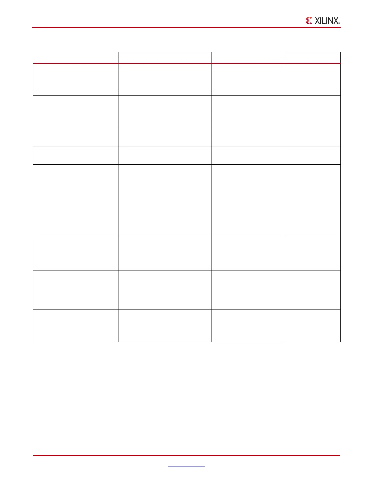
CLKOUT_PHASE_SHIFT This attribute specifies the phase-
shift mode.
String: NONE or FIXED or
VARIABLE_POSITIVE or
VARIABLE_CENTER or
DIRECT
NONE
DESKEW_ADJUST This affects the amount of delay in
the feedback path, and should be
used for source-synchronous
interfaces.
String:
SYSTEM_SYNCHRONOUS
or
SOURCE_SYNCHRONOUS
SYSTEM_
SYNCHRONOUS
DFS_FREQUENCY_MODE This specifies the frequency mode of
the frequency synthesizer.
String: LOW or HIGH LOW
DLL_FREQUENCY_MODE This specifies the frequency mode of
the DLL.
String: LOW or HIGH LOW
DUTY_CYCLE_CORRECTION This controls the DCM 1X outputs
(CLK0, CLK90, CLK180, and
CLK270), to exhibit a 50/50 duty
cycle. Leave this attribute set at the
default value.
Boolean: TRUE or FALSE TRUE
DCM_PERFORMANCE_MODE Allows selection between maximum
frequency/ minimum jitter, and low
frequency/maximum phase-shift
range
String: MAX_SPEED or
MAX_RANGE
MAX_SPEED
FACTORY_JF DLL_FREQUENCY_MODE=LOW
default (0xF0F0).
DLL_FREQUENCY_MODE=HIGH
default (0x
F0F0).
BIT_VECTOR
0xF0F0
PHASE_SHIFT This specifies the phase-shift
numerator. The value range
depends on
CLKOUT_PHASE_SHIFT and clock
frequency.
Integer: –255 to 1023 0
STARTUP_WAIT When this attribute is set to TRUE,
the configuration startup sequence
waits in the specified cycle until the
DCM locks.
Boolean: FALSE or TRUE FALSE
Table 2-6: DCM Attributes (Continued)
DCM Attribute Name Description Values Default Value
 Loading...


