Refer to:
• Table 63 for the insulation removal length
• Figure 24
• Subject 20-00-15 for the insulation removal procedures.
(5) For butt splices with an insulation grip, put the wire in the splice.
Refer to:
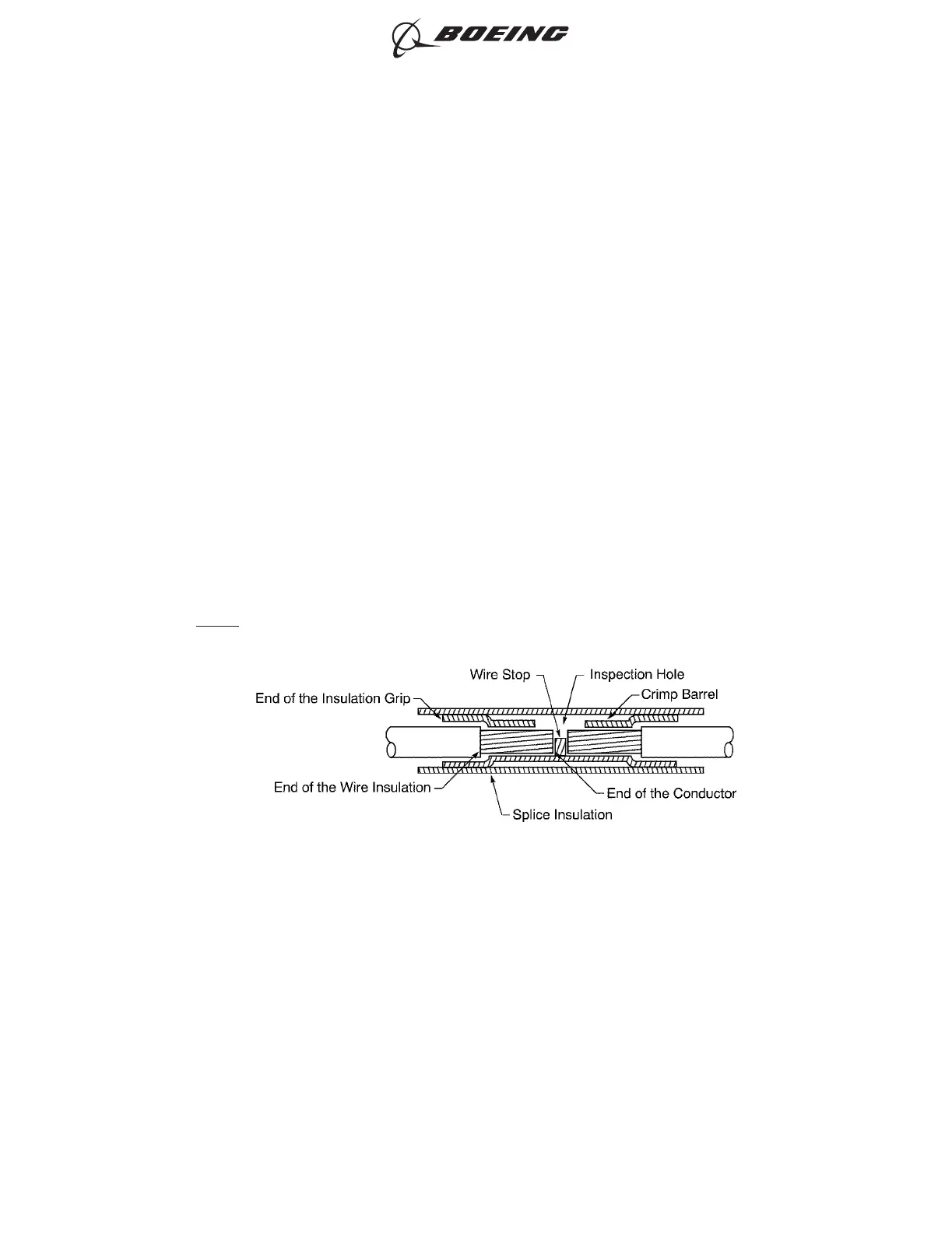
• Figure 25 for the position of the wire in the splice with the wire insulation in the insulation
grip
• Figure 26 for the position of the wire in the splice with the wire insulation out of the
insulation grip.
Make sure that:
• The end of the conductor can be seen in the inspection hole
• The end of the conductor does not make an overlap with the wire stop
• The wire insulation is not in the crimp barrel
• If the wire insulation can go into the insulation grip, the insulation grip makes an overlap with
the wire insulation
• If the wire insulation cannot go into the insulation grip, the end of the wire insulation is a
maximum of 0.13 inch from the end of the insulation grip
• The splice insulation makes an overlap with the wire insulation.
NOTE: The wire insulation, the crimp barrel, and the conductor can be seen through the
insulation of the butt splice.
POSITION OF THE WIRE IN THE SPLICE WITH THE WIRE INSULATION IN THE INSULATION GRIP
Figure 25
ASSEMBLY OF SPLICES
707, 727-787
STANDARD WIRING PRACTICES MANUAL
20-30-12
Page 68
Feb 15/2021D6-54446
ECCN 9E991 BOEING PROPRIETARY - See title page for details