(6) For butt splices without an insulation grip, put the wires in the splice. Refer to Figure 29.
Make sure that for each wire:
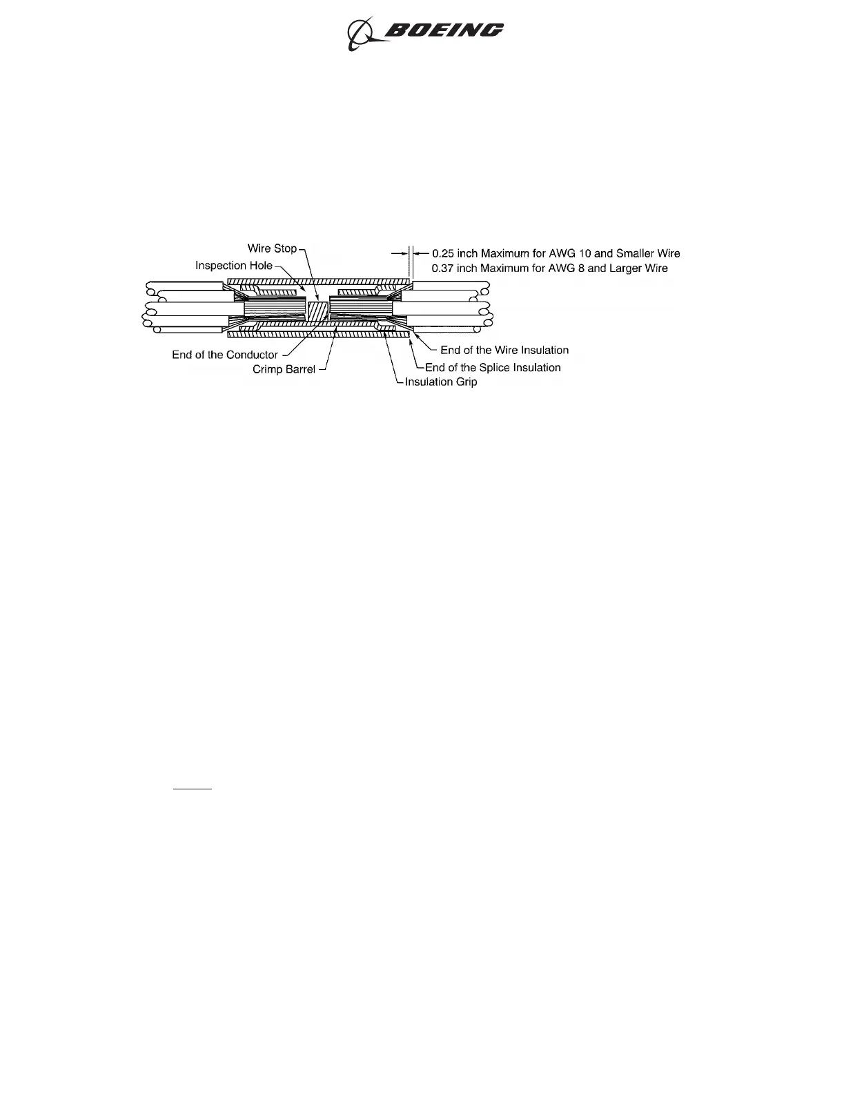
• The end of the conductor can be seen in the inspection hole
• The end of the conductor does not make an overlap with the wire stop
• The wire insulation is not in the crimp barrel
• If the wire insulation can go into the splice insulation, the splice insulation makes an overlap
with the wire insulation
• If the wire insulation of a AWG 10 and smaller wire cannot go into the splice insulation, the
end of the wire insulation is a maximum of 0.25 inch from the end of the splice insulation
• If the wire insulation of a AWG 8 and larger wire cannot go into the splice insulation, the end
of the wire insulation is a maximum of 0.37 inch from the end of the splice insulation.
NOTE: The wire insulation, the crimp barrel, and the conductor can be seen through the
insulation of the butt splice.
POSITION OF THE WIRES IN THE INSULATED BUTT SPLICE WITH AN INSULATION GRIP
Figure 28
ASSEMBLY OF SPLICES
707, 727-787
STANDARD WIRING PRACTICES MANUAL
20-30-12
Page 71
Feb 15/2021D6-54446
ECCN 9E991 BOEING PROPRIETARY - See title page for details