(7) If it is necessary, remove more insulation from the wire to make a correct fit of the wire in the
splice.
(8) If the end of a wire insulation is not in the splice insulation, put a sleeve on the splice assembly.
(a) Make a selection of a Temperature Grade B sleeve. Refer to Table 51.
Make sure that the sleeve has the smallest diameter that can be put on the wires and the
splice.
(b) Cut a length of the sleeve.
Make sure that the sleeve makes a 0.8 inch minimum overlap with the wire insulation on
each wire on each end of the splice assembly.
(c) Put the sleeve on the wires on one side of the splice assembly.
(9) Assemble one end of the splice.
(a) Put the splice in the crimp tool.
(b) Hold the splice in position with light pressure.
(c) Put the wires in the end of the splice.
Make sure that the wires are in the correct position.
(d) Crimp the splice.
(10) Do Step 6.C.(9) again to assemble the other end of the splice.
(11) If a sleeve is on the wires, install the sleeve on the splice assembly.
(a) Align the center of the sleeve with the center of the splice.
(b) Shrink the sleeve into position. Refer to Subject 20-10-14.
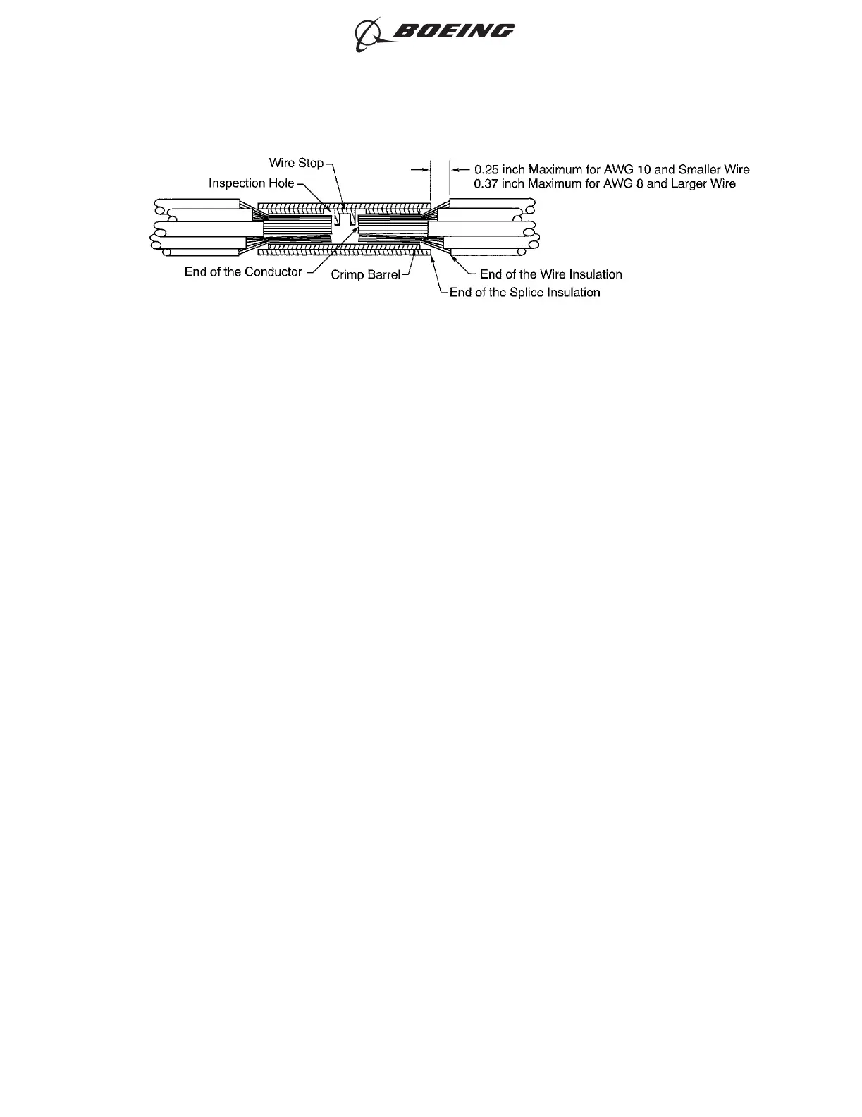
POSITION OF THE WIRE IN THE INSULATED BUTT SPLICE
Figure 29
ASSEMBLY OF SPLICES
707, 727-787
STANDARD WIRING PRACTICES MANUAL
20-30-12
Page 72
Feb 15/2021D6-54446
ECCN 9E991 BOEING PROPRIETARY - See title page for details