(e) Crimp the splice.
(7) Do Step 7.B.(6) again to assemble the other end of the butt splice.
(8) Put three layers of the insulation tape on the splice assembly.
(a) Tightly wind the first layer of tape on the splice assembly.
NOTE: An alternative to the first layer of tape is two layers of Temperature Grade D
insulation film strip from Table 54.
Make sure that:
• The layer of tape or each layer of film strip starts 0.5 inch minimum farther than the
end of the wire insulation
• The layer of tape or each layer of film strip stops 0.5 inch minimum farther than the
end of the wire insulation at the other end of the splice assembly
• The layer of tape or each layer of film strip makes a 50 percent overlap
• The second layer of film strip is wound in the opposite direction of the first layer.
(b) Tightly wind the second layer of tape on the splice assembly in the opposite direction of the
first layer.
Make sure that the layer of tape:
• Starts 1 inch minimum farther than the end of the first layer of tape
• Stops 1 inch minimum farther than the end of the first layer of tape at the other end of
the splice assembly
• Makes a minimum 50 percent overlap.
(c) Tightly wind the third layer of tape on the splice assembly in the opposite direction of the
second layer.
Make sure that the layer:
• Starts where the second layer stops
• Stops where the second layer starts
• Makes a 50 percent overlap.
(9) Assemble a lacing tape wire harness tie on each end of the splice assembly approximately 0.25
inch from the end of the tape. Refer to Subject 20-10-11.
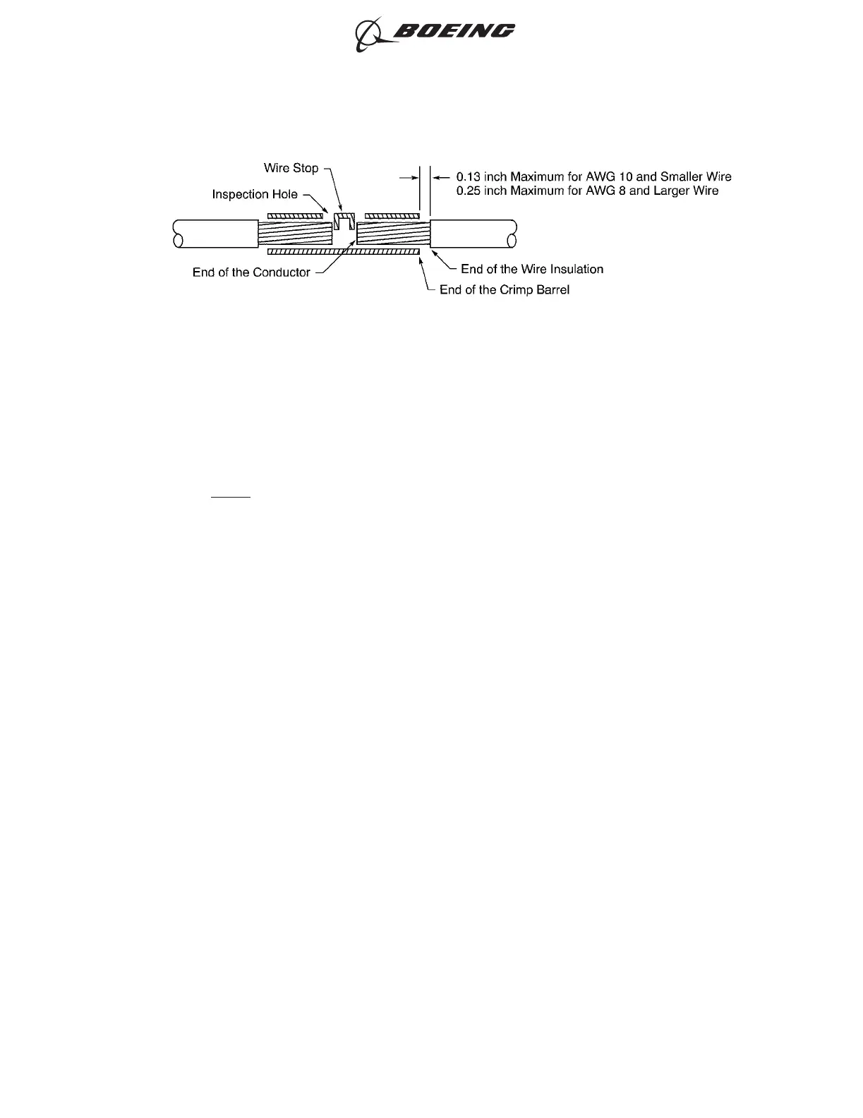
POSITION OF THE WIRE IN THE BUTT SPLICE
Figure 42
ASSEMBLY OF SPLICES
707, 727-787
STANDARD WIRING PRACTICES MANUAL
20-30-12
Page 83
Feb 15/2021D6-54446
ECCN 9E991 BOEING PROPRIETARY - See title page for details