Table 70 INSULATION REMOVAL LENGTH (Continued)
Splice Part Number
Insulation Removal Length L
(inch)
Target Tolerance
D-609-06 0.28 ±0.03
D-609-07 0.28 ±0.03
D-609-08 0.28 ±0.03
NAS1387-4 0.28 ±0.03
NAS1387-5 0.28 ±0.03
NAS1387-6 0.28 ±0.03
(6) Wind a layer of the insulation tape on each of the two wires for the side of the splice with two
wires.
Make sure that:
• The edge of the tape is aligned with the end of the wire insulation
• The tape goes around the circumference of the wire a minimum of two times
• The tape makes a 100 percent overlap.
(7) Assemble one end of the butt splice.
(a) Put the splice in the crimp tool.
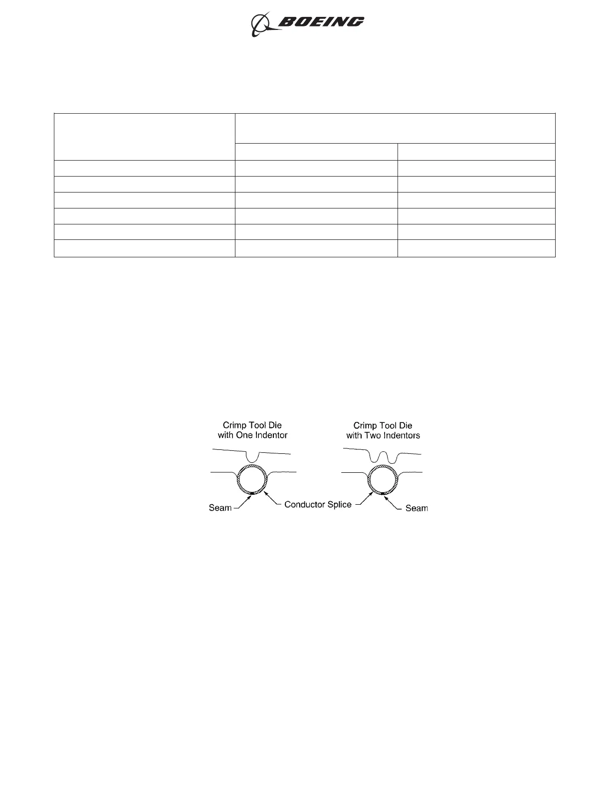
(b) If the splice has a seam, align the seam opposite the indenter. Refer to Figure 51.
(c) Hold the splice in position with light pressure.
(d) Put the wire or wires in the splice. Refer to Figure 52.
Make sure that:
• The end of the conductor can be seen in the inspection hole
• The end of the conductor does not make an overlap with the wire stop
• The insulation of the wire is not in the crimp barrel
• For AWG 10 and smaller wire, the end of the wire insulation is a maximum of 0.13 inch
from the end of the crimp barrel
POSITION OF THE BUTT SPLICE IN THE CRIMP TOOL
Figure 51
ASSEMBLY OF SPLICES
707, 727-787
STANDARD WIRING PRACTICES MANUAL
20-30-12
Page 90
Feb 15/2021D6-54446
ECCN 9E991 BOEING PROPRIETARY - See title page for details