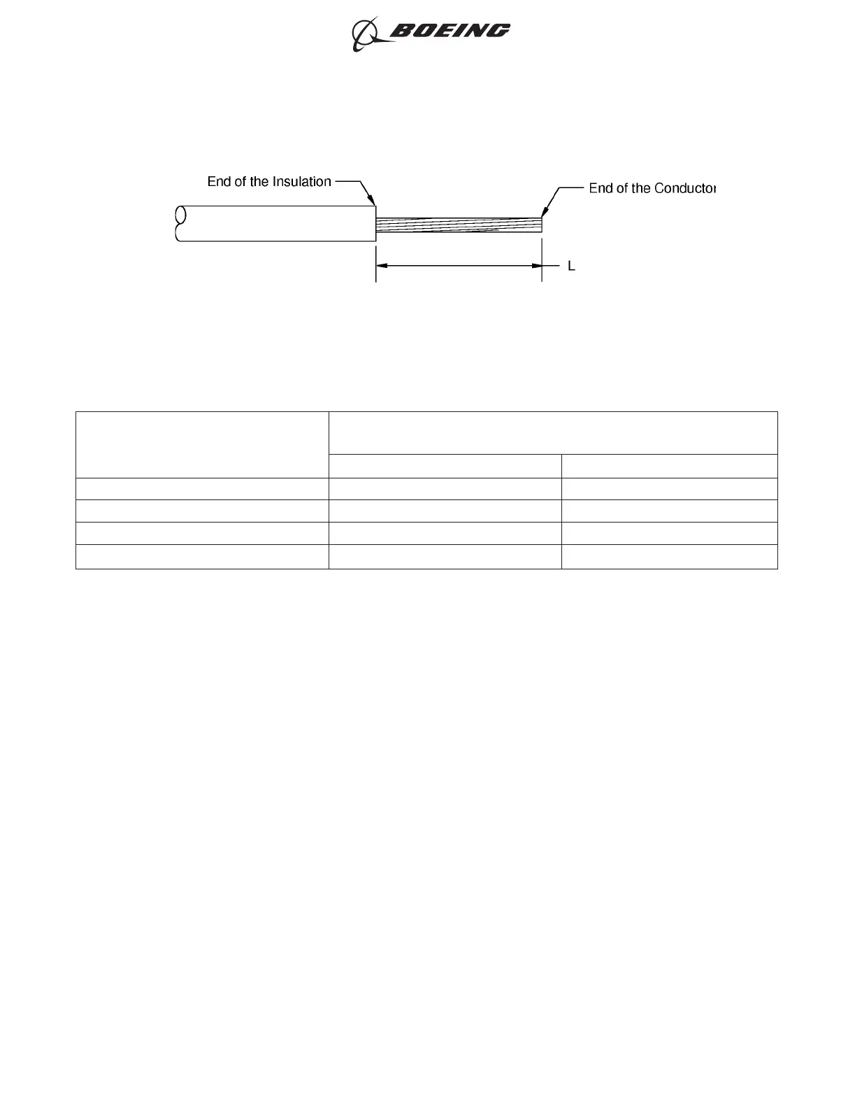
Table 73
INSULATION REMOVAL LENGTH
Butt Splice Part Number
Insulation Removal Length L
(inch)
Target Tolerance
D-609-06 0.28 ±0.03
D-609-07 0.28 ±0.03
D-609-08 0.28 ±0.03
D-609-10 0.28 ±0.03
(7) Assemble one end of the butt splice.
(a) Put the splice in the crimp tool.
(b) Hold the splice in position with light pressure.
(c) Put all of the wires for one end of the splice in the crimp barrel. Refer to Figure 63 and
Figure 64.
Make sure that:
• The end of each conductor can be seen in the inspection hole
• The end of each conductor does not make an overlap with the wire stop
• The insulation of each wire is not in the crimp barrel
• For one wire, the end of the wire insulation is a maximum of 0.13 inch from the end of
the crimp barrel
• For two wires, the end of the wire insulation is a maximum of 0.25 inch from the end of
the crimp barrel.
INSULATION REMOVAL LENGTH
Figure 62
ASSEMBLY OF SPLICES
707, 727-787
STANDARD WIRING PRACTICES MANUAL
20-30-12
Page 99
Feb 15/2021D6-54446
ECCN 9E991 BOEING PROPRIETARY - See title page for details