Refer to:
• Figure 67
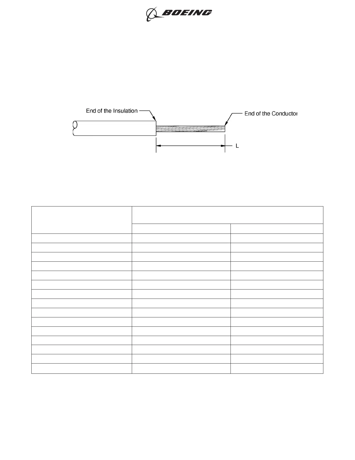
• Table 74 for the insulation removal length
• Subject 20-00-15 for the insulation removal procedures.
Table 74
INSULATION REMOVAL LENGTH
Splice Part Number
Insulation Removal Length L
(inch)
Target Tolerance
BACT12C101 0.72 ±0.03
BACT12C12 0.34 ±0.03
BACT12C21 0.65 ±0.03
BACT12C4 0.53 ±0.03
BACT12C4NK 0.47 ±0.03
BACT12C6 0.53 ±0.03
BACT12C6NK 0.53 ±0.03
BACT12C8 0.47 ±0.03
BACT12C8NK 0.53 ±0.03
D-609-06 0.28 ±0.03
D-609-07 0.28 ±0.03
D-609-08 0.28 ±0.03
NAS1387-4 0.28 ±0.03
NAS1387-5 0.28 ±0.03
NAS1387-6 0.28 ±0.03
(8) Assemble one end of the butt splice.
(a) Put the splice in the crimp tool.
(b) If the splice has a seam, align the seam opposite the indenter. Refer to Figure 68.
INSULATION REMOVAL LENGTH
Figure 67
ASSEMBLY OF SPLICES
707, 727-787
STANDARD WIRING PRACTICES MANUAL
20-30-12
Page 102
Feb 15/2021D6-54446
ECCN 9E991 BOEING PROPRIETARY - See title page for details