Make sure that the sleeve has the smallest diameter that can be put on the splice assembly.
NOTE: For alternative heat shrinkable sleeves, refer to Subject 20-00-11.
(8) Cut the necessary length of the sleeve.
Make sure that the sleeve extends a minimum of 1.1 inches farther than each end of the splice.
(9) Put the sleeve on the wire of one end of the splice assembly.
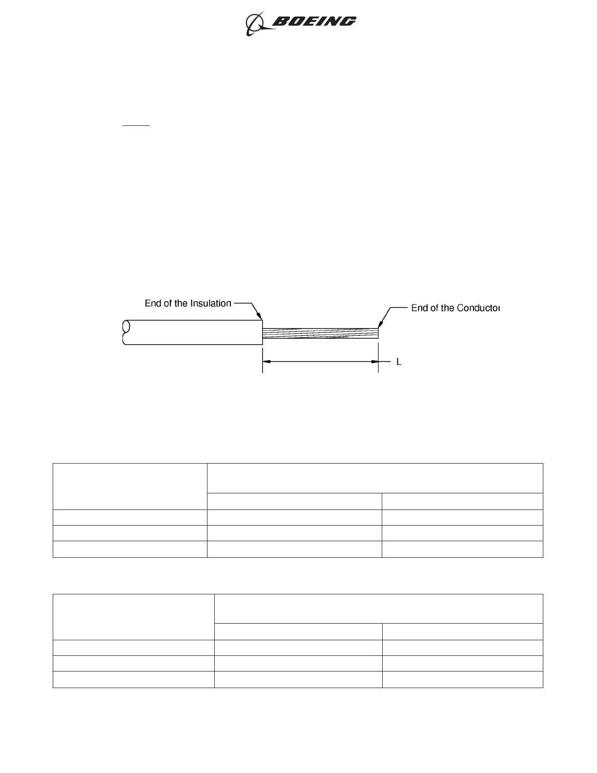
(10) Remove the necessary length of insulation from the end of the wires.
Refer to:
• Figure 98
• Table 81 for the insulation removal length for a wire that can go into the insulation grip
• Table 82 for the insulation removal length for a wire that cannot go into the insulation grip
• Subject 20-00-15 for the insulation removal procedures.
Table 81
INSULATION REMOVAL LENGTH FOR A WIRE THAT CAN GO INTO THE INSULATION GRIP
Splice Part Number
Insulation Removal Length L
(inch)
Target Tolerance
BACT12C11 0.37 ±0.02
BACT12C15 0.23 ±0.02
BACT12C20 0.23 ±0.02
Table 82
INSULATION REMOVAL LENGTH FOR A WIRE THAT CANNOT GO INTO THE INSULATION GRIP
Splice Part Number
Insulation Removal Length L
(inch)
Target Tolerance
BACT12C11 0.46 ±0.02
BACT12C15 0.30 ±0.02
BACT12C20 0.30 ±0.02
INSULATION REMOVAL LENGTH
Figure 98
ASSEMBLY OF SPLICES
707, 727-787
STANDARD WIRING PRACTICES MANUAL
20-30-12
Page 125
Jun 15/2021D6-54446
ECCN 9E991 BOEING PROPRIETARY - See title page for details