(7) Prepare each wire for the side of the splice assembly with two wires.
Table 83
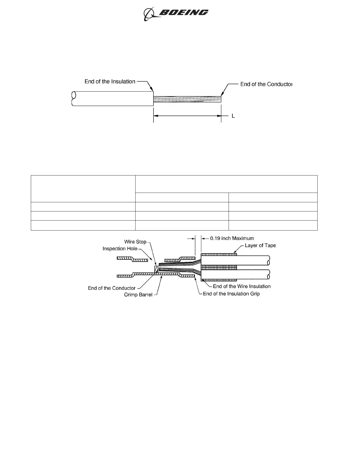
INSULATION REMOVAL LENGTH
Splice Part Number
Insulation Removal Length L
(inch)
Target Tolerance
BACT12C11 0.46 ±0.02
BACT12C15 0.30 ±0.02
BACT12C20 0.30 ±0.02
(a) Remove the necessary length of insulation from the end of each wire.
Refer to:
• Figure 102
• Table 83 for the insulation removal length
• Subject 20-00-15 for the insulation removal procedures.
(b) Put the wires in the splice. Refer to Figure 103.
Make sure that:
• The end of each conductor can be seen in the inspection hole
INSULATION REMOVAL LENGTH
Figure 102
POSITION OF THE WIRES IN THE BUTT SPLICE
Figure 103
ASSEMBLY OF SPLICES
707, 727-787
STANDARD WIRING PRACTICES MANUAL
20-30-12
Page 129
Jun 15/2021D6-54446
ECCN 9E991 BOEING PROPRIETARY - See title page for details