Table 100
INSULATION REMOVAL LENGTH
Splice Part Number
Insulation Removal Length L
(inch)
Target Tolerance
BACT12C11 0.46 ±0.02
BACT12C15 0.30 ±0.02
BACT12C20 0.30 ±0.02
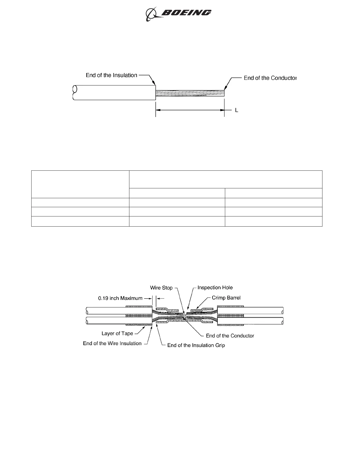
(6) Put the wires in the splice. Refer to Figure 144.
Make sure that:
• The end of each conductor can be seen in the inspection hole
• The end of each conductor does not make an overlap with the wire stop
• The end of each wire insulation is a maximum of 0.19 inch from the end of the insulation
grip.
(7) If it is necessary, remove more insulation from the end of the wire.
(8) Wind a layer of the insulation tape on each wire. Refer to Figure 144.
Make sure that:
INSULATION REMOVAL LENGTH
Figure 143
POSITION OF THE WIRES IN THE BUTT SPLICE
Figure 144
ASSEMBLY OF SPLICES
707, 727-787
STANDARD WIRING PRACTICES MANUAL
20-30-12
Page 168
Jun 15/2021D6-54446
ECCN 9E991 BOEING PROPRIETARY - See title page for details