(7) Prepare the lengths of the wires of the cable for each of the sealed wire splices. If the locations of
the sealed splices are not specified, refer to Figure 254.
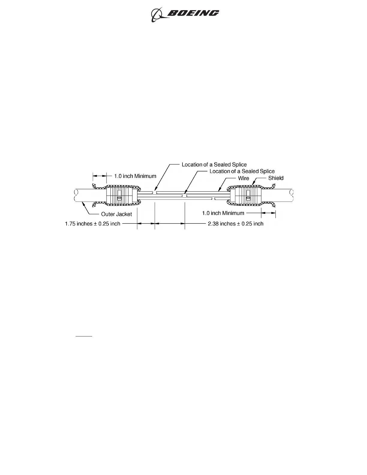
If the locations of the sealed splices are not specified, make sure that:
• The distance from the end of the jacket to the center of the nearest sealed splice is 1.75
inches ±0.25 inch
• The distance from the center of a sealed splice on one wire to the center of the nearest
sealed splice on another wire is 2.38 inches ±0.25 inch.
(8) If it is not specified, make a selection of a Temperature Grade D shield sleeve material from Table
57.
Make sure that the shield sleeve material has the smallest diameter that can go on the folded
back shield on the shield termination ring.
NOTE: For alternative shield sleeve materials, refer to Subject 20-00-11.
(9) Make a selection of a Temperature Grade D heat shrinkable sleeve from Table 51
Make sure that the heat shrinkable sleeve has the smallest diameter that can go on the
completed splice assembly.
(10) Cut the necessary length of the shield sleeve material.
Make sure that the ends of the shield sleeve material extend a minimum of one inch farther than
the rear end of each shield termination ring.
(11) Put the heat shrinkable sleeve and the shield sleeve material on the end of the other cable. Refer
to Figure 255.
PREPARATION OF THE SHIELDED CABLE
Figure 254
ASSEMBLY OF SPLICES
707, 727-787
STANDARD WIRING PRACTICES MANUAL
20-30-12
Page 284
Jun 15/2021D6-54446
ECCN 9E991 BOEING PROPRIETARY - See title page for details